
|
This file is available on a Cryptome DVD offered by Cryptome. Donate $25 for a DVD of the Cryptome 10-year archives of 35,000 files from June 1996 to June 2006 (~3.5 GB). Click Paypal or mail check/MO made out to John Young, 251 West 89th Street, New York, NY 10024. Archives include all files of cryptome.org, cryptome2.org, jya.com, cartome.org, eyeball-series.org and iraq-kill-maim.org. Cryptome offers with the Cryptome DVD an INSCOM DVD of about 18,000 pages of counter-intelligence dossiers declassified by the US Army Information and Security Command, dating from 1945 to 1985. No additional contribution required -- $25 for both. The DVDs will be sent anywhere worldwide without extra cost. | |||
Space Handbook
_____________________________________________________
The Air Force views space as a medium, like the air or sea, in which to carry out different types of missions. Air Force doctrine specifically integrates space missions into the four basic roles performed by aerospace forces: force support, force enhancement, aerospace control, and force application.
This chapter defines space missions associated with each of the four roles. Next is a brief description of the military space systems involved in the execution of space missions.1
Force support, the ability to sustain forces, includes the space mission of on-orbit support for satellites.2 During the entire life of any satellite or military space system, from prelaunch checkout to on-orbit operations, there is a requirement for constant control, support, and direction of the satellite and its assigned mission. The Air Force maintains this critical operations capability through the Air Force Satellite Control Network (AFSCN).
The AFSCN is a global system to provide command, control, and communications for space vehicles (SV). The AFSCN consists of dedicated and common-user equipment and facilities which, collectively, provide operational telemetry, tracking, and commanding (TT&C) support for virtually all Department of Defense (DOD) SVs plus selected National Aeronautics and Space Administration (NASA) and foreign allied nations' space programs. DOD space programs support requirements of the national command authorities (NCA), the Joint Chiefs of Staff, and the unified and specified war-fighting commanders under peacetime and wartime conditions. In addition to providing TT&C support, the AFSCN processes and distributes satellite mission data to the appropriate users and provides research and development (R&D) support for space test activities.3
Satellite command and control is the essential mission of the AFSCN. To accomplish this complex task, various control centers are organized to integrate incoming and outgoing satellite control data for decision making. The complexity of the AFSCN mission increases with the number of active satellite missions.4 Supporting resources of the AFSCN consist of leased and allocated communications, and host-base-provided facilities and utilities.5
Elements of the AFSCN generally fall into two groups: (1) dedicated elements that support a single space program or military space system and (2) common-user elements that support a number of different space programs or military space systems. Most of these elements are at fixed locations throughout the world, but the AFSCN can deploy a number of transportable assets whenever and wherever military forces need them.6
Dedicated elements specific to one satellite system support dedicated programs. A dedicated program is a closed system with separate control centers and remote tracking hardware. Two examples of dedicated satellite programs supported by dedicated elements are the Defense Meteorological Satellite Program (DMSP) and the Global Positioning System (GPS) satellite program. The dedicated control centers for DMSP are located at Fairchild Air Force Base (AFB), Washington, and the Multi-Purpose Satellite Operations Center (MPSOC) at Offutt AFB, Nebraska. The dedicated control center for the GPS program, known as the Master Control Station (MCS). is located at Falcon AFB. Colorado.7
Common-user elements of the AFSCN include a wide variety of assets strategically located around the world. These elements consist of command posts, mission control centers, resource control centers, and remote tracking stations, as well as various communication links, computer facilities, and training and testing facilities. These elements support multiple programs. The principle common-user mission control centers and command posts are located at Falcon AFB, Colorado, and Onizuka AFB, California.8
The AFSCN has the ability and flexibility to support continuously a wide variety of space vehicles in various orbits and altitudes. Operations support for satellite missions and limited ballistic/suborbital vehicle flights generally fit into five categories.9
Low-altitude satellites are characterized by near-polar orbits, with altitudes ranging from 100 to 200 nautical miles. Their operational lifetimes are short, and the satellites have a short pass duration (2.5 to 10 minutes per tracking station). They are the most dynamic of all vehicles supported, requiring frequent command message transmission.
Medium-altitude satellites generally have an orbital inclination of near 90 degrees, with altitudes ranging from 200 to 10,000 nautical miles. These satellites average one tracking station contact every other revolution, with a pass duration ranging from 10 to 20 minutes. Planned support is for one year or longer.
High-altitude satellites usually have low-inclination (equatorial) orbits, with altitudes exceeding l0,000 nautical miles (NM). Their operational lifetimes are measured in years. Because of varied servicing support requirements, a support period (pass) may vary from five minutes to several hours.
Included in the next category are ballistic missiles and suborbital test vehicles usually launched from the Western Space and Missile Center at Vandenberg AFB, California. Tracking and telemetry data for ascent and mid-course flight phases are recorded by the appropriate remote tracking stations (RTS). Total support time varies from 10 to 30 minutes. This kind of support requires considerable planning and readiness testing from the AFSCN.
The AFSCN supports certain orbital vehicles during launch and ascent or during ascent only. Support may vary from 10 minutes to 16 hours (continuous), depending on a vehicle's orbital characteristics and the support requirements levied. Tracking and telemetry data retrieval is the primary support objective.
The task of the satellite operations centers (SOC) is to provide prelaunch, launch, early orbit, anomaly resolution, and operational TT&C support to all assigned space vehicle mission. Twelve functions are associated with satellite control:
1. satellite orbit determination,2. ephemeris data generation,
3. command load assembly,
4. pass planning,
5. pass plan brief to tracking station,
6. satellite acquisition and tracking,
7. satellite commanding,
8. telemetry data retrieval,
9. data analysis,
10. satellite health and status determination,
11. corrective action determination, and
12. satellite data transfer to users.10
SOCs consist of hardware, software, and personnel that interact to accomplish these space support operations: resource control, mission control support, and communications control functions. Certain SOCs at Onizuka AFB, California, provide backup capability to Falcon AFB SOCs, while others are dedicated to unique programs not part of the AFSCN. Each SOC provides service for one or more specific satellite programs. Although the capabilities of SOCs vary, each is configured to support multiple satellite contacts simultaneously and/or to carry out premission rehearsals or exercises based on assigned satellite programs.
SOCs are physically isolated from each other but are electrically connected to allocated range resources. The SOCs at Onizuka AFB are connected to the resource control complex (RCC) at Onizuka AFB, and the SOCs at Falcon are connected to the RCC at Falcon AFB. During a satellite contact, mission personnel exercise direct control of the assigned resources through on-line workstations in the SOC that access processing equipment, interactive controls, computer programs, and interfaces to internal and external elements. An SOC usually has two mainframe computers, one acting as a contact support processor and the other as a planning and evaluation processor. These processors, with associated software, carry out planning, contact support, evaluation, training and rehearsal, simulation, data base management, and system development.
SOC satellite operations divide into three distinct phases: planning, pass support (i.e., operational satellite contact), and evaluation. The usage of the termpass as inpass support evolved from early space operations history when satellites would "pass by" as they moved in orbit from horizon to horizon relative to the operators. The length of these phases, especially pass support, varies widely depending on the type of satellite supported, its orbital geometry, and individual mission support requirements (fig. 1). The following is an overview of these phases.11
Source: Maj Theodore W. Burgner, "Space Handbook" (Paper provided
as input for revision of
Space Handbook, Operations Training Division, 45th Space Wing , August
1991), 37.
Figure 1. Satellite Support Functional Flow
The planning phase mainly involves activities conducted by the SOC and the RCC. The SOC develops an overall contact support plan (CSP) and identifies what is required to support a particular satellite contact. The CSP includes resource requirements, telemetry parameters, and command and ephemeris data. The SOC may simultaneously prepare multiple satellite support plans. The result of this planning effort is requests by the SOCs and other users to the RCC for AFSCN resources. The RCC then produces a schedule for all AFSCN satellite support based on resources and priorities. There are both long-range and near-term schedules that dictate what resources can support specific satellite passes. Resource scheduling is an ongoing activity. There are opportunities throughout the planning phase to deconflict complex satellite pass support requirements.
The pass support phase includes both prepass and satellite contact time. The SOC, RCC, RTS, and communications elements act in concert to configure all resources, conduct readiness testing, and place the systems into final configuration for the actual satellite support (pass).
The SOC mission control team (MCT) initiates the prepass by requesting that the network communications voice operator establish communications nets. When the operator establishes the nets, the MCT members log on to their respective computer terminals to configure hardware and software. The MCT crew commander provides a briefing over an operations (OPS) communications net and the MCT ground controller (GC) briefs over another communications net, termed the configuration net. The GC briefs the RCC resource controller (RC), the lead communications operator (LCO), the Defense Communications System/Satellite Control Facility Interface System (DSIS) operator, the wideband operator, and the RTS antenna operator on data rates, communications and data channel activity, and overall resource configuration for the particular support. Upon briefing completion, the LCO, DSIS, and wideband operators perform channel checks. The RC then performs commanding, telemetry, and antenna slaving tests. The GC then performs similar readiness testing. During the testing period, all of the above elements are involved in the prepass checks and assist in troubleshooting and reconfiguring, if necessary. The RTS antenna is then positioned in preparation for satellite acquisition. Satellite contact begins when the RTS acquires and tracks the satellite. RTS makes contact by either sending out a turn-on command to activate satellite signals or by simply receiving transmitted satellite signals. The RTS in turn relays satellite telemetry data to the SOC while the RCC and communications elements monitor the operations in progress. The MCT evaluates the telemetry data in real time and verifies user data reception. The MCT may send commands to the satellite via the RTS according to the pass plan. The support ends when the objectives are met and the MCT commander directs the RTS to terminate tracking of the satellite.
The evaluation phase is also the postpass phase. While the communications nets are still operating, the MCT crew commander discusses any support-related problems with the RTS, verifies the next pass time, and calls the network configuration voice operator to terminate the OPS net. The GC discusses any pass-related problems with people on the configuration net and releases the net participants through the RC. When the LCO notifies the RC that resources are normalized, and the MCT crew commander has directed the communications operators (wideband, DSIS, LCO, etc.) to terminate both nets, time-critical postpass activities are concluded, and the RTS and communications links are then available for another support. The MCT may continue such evaluation activities as analyzing payload data, satellite performance, data quality, and orbital parameters.
Remote tracking stations provide the satellite-to-ground interface for satellite command and control; they provide the actual TT&C contact with any space vehicle supported by the AFSCN. The contact is accomplished under the direction of a SOC. The RTS relays satellite telemetry to the control complex, either generates commands for or relays commands to the satellite, and provides tracking data to the control complex. The specific RTS tasks vary depending on the communications interface and the mission. AFSCN RTSs are located worldwide and provide prelaunch, launch and early orbit, and on-orbit TT&C support for assigned US and allied satellites, ballistic missile launches, and the Space Transportation System (STS)--the space shuttle.12
RTSs are strategically located at nine sites with 16 antennas to maximize area coverage for timely and effective use of RTS resources as well as for flexible, multiple support capability (fig. 2). The RTSs are available to control complexes on a time-shared basis for supporting satellite operations and are a scheduled resource. Scheduling is accomplished by the RCC at either Falcon AFB or Onizuka AFB. The RCC allocates time to each RTS for operations, maintenance, and training.

Source: Maj Theodore W. Burgner, "Space Handbook" (Paper provided
as input for revision of
Space Handbook, Operations Training Division, 45th Space Wing , August
1991),24.
Figure 2. Remote Tracking Station Locations
The RTSs within the AFSCN have been modernized as automated remote tracking stations (ARTS). ARTS sites may be a new site, such as the Colorado Tracking Station at Falcon AFB, or a modernized existing RTS site, such as the Vandenberg Tracking Station. All RTSs or ARTSs, while not identical in physical layout, function in approximately the same manner. Some RTSs are configured with additional equipment to support unique missions. We can visualize an RTS's antenna coverage as a cone, widening as the distance from Earth becomes greater. With higher satellite altitudes, a wider selection of RTSs can support a given satellite contact.
RTSs are functionally equivalent to each other and are scheduled for operations based on satellite support needs and the visibility of the satellite to the RTS. Satellite operations events such as TT&C directives, vehicle status and health, and SV commanding data--all pass between the mission control centers and the RTSs over communications links. The RTS uplink transmits satellite command data upload and ranging data. Satellite telemetry and ranging are received in as many as four simultaneous downlinks and transmitted via the communications system to control complexes.
The telemetry function involves tracking in the reception of information on the health, status, and mission payload telemetry of a satellite. An RTS receives satellite telemetry data and transmits this data to a control center. The tracking function involves satellite location and velocity determination. Antenna azimuth and elevation pointing data direct the antenna for satellite acquisition. After acquisition, the RTS transfers range and range-rate data, antenna pointing data, and status information to the control centers, usually via the DSIS. The SOC uses control center tracking data to predict future satellite contacts and to generate antenna pointing data, for real-time acquisition by remote tracking antennas.
The command function includes transmitting coded signals to a satellite to do such things as fire thrusters, start or stop mission tasks, switch power sources, or update sequence programs. The SOC transfers encrypted or clear blocks of command data to the RTS for transmission to the SV. Verification and authentication for each command is normally within the satellite telemetry transmission to the RTS ground antenna and back to the SOC. The SOC then verifies that the satellite properly received the transmitted commands.
Remote Tracking Station Communications. Each RTS has communications capabilities that provide primary and alternate connectivity for data and voice circuits to and from control complexes. One capability is to encrypt and decrypt information and to communicate intrastation via intercom or telephone. Primary communication is accomplished using the DSIS, which links the RTS, via the Defense Satellite Communications System (DSCS) or commercial communication satellites, with either Falcon or Onizuka AFB. Alternate communications links carry digital voice and data, usually on leased commercial telephone circuits, between all AFSCN RTSs and external users. The capabilities of these links vary considerably depending on the support requirements of the different control complexes. An additional communications system used by the AFSCN is called Mission-22 (M-22). It uses DOD host vehicles that are in highly elliptical orbits. Just as the AFSCN is a complex assembly of elements supporting US space assets, the communications links required to carry out the AFSCN mission are a complex suite of networks within and between all elements of the AFSCN and external users. These communications links provide communications security, redundancy, data recording, and interface capability with communications satellites, land lines, fiber optics, and microwave circuits for transmission of data, voice, teletype, and facsimile information.
The wideband communications network provides the primary communications links used in the AFSCN between the control centers and the RTSs. This network uses the DSIS, which links the RTS via DSCS II and DSCS III satellites or commercial communication satellites with either Falcon or Onizuka AFBs. DSIS provides high data rate communications between the RTSs and the control centers. Narrowband communications are an alternative to the wideband system for data and digital voice capability. Additionally, the network uses M-22 communications satellites that provide the capability of minimum essential wideband support in the event of any wideband link outages to any RTS. Some RTSs have a data link terminal (DLT) to specifically utilize M-22. An RTS with two antennas, but no DLT, can still use M-22 for real-time transmission if one antenna tracks, while the other relays data via M-22. The M-22 data rate is limited, but its capability fulfills most present and future vehicle reception requirements.
Remote Tracking Station--Mission Unique Interfaces. RTSs also interface with dedicated elements within the AFSCN in support of specific requirements of the DMSP and GPS programs. Specific mission unique interfaces at the Thule (Greenland), Hawaii, and New Hampshire RTSs provide DMSP support. The RTSs provide an interface for command and telemetry data between the RTSs and the dedicated DMSP elements. The dedicated elements of the DMSP are the Multi-Purpose Satellite Operations Center and the Fairchild Satellite Operations Center. The RTSs provide an interface for primary mission data recovery for transmission to the Air Force Global Weather Central, as well as to the Navy Fleet Numerical Oceanography Center.
A mission unique enhancement at the Colorado Tracking Station (CTS) provides GPS program support. This mission unique interface provides the CTS with a GPS ground antenna command and telemetry processing capability--which allows the GPS SOC at Falcon AFB to directly control the CTS.
There are two command centers in the AFSCN: the Wing Command Post (WCP) located at Falcon AFB and the Group Operations Center (OC) at Onizuka AFB. The WCP exercises operational control over the AFSCN. The OC provides backup functions for the WCP and primary operational control over selected programs specific to Onizuka AFB.13
The Wing Command Post' s primary job is to support the 50th Space Wing commander, providing a command post for the 50th Space Wing and Falcon AFB. The wing commander requires this command post to fulfill responsibilities as the manager and operator of the unique worldwide AFSCN. The WCP also links assigned AFSCN assets into a fully responsive, integrated system supporting multi-service and multi-agency programs and serves as the focal point through which the Air Force Space Command (AFSPACECOM) commander exercises real-time combatant command over AFSCN forces. Some of the functions carried out by the WCP include
1. monitoring and reporting space system health, status, and readiness information of AFSCN elements including dedicated centers and AFSCN mobile resources,2. implementing operations plans and contingency plans,
3. disseminating AFSCN element hostile attack warnings,
4. disseminating intelligence information affecting satellite control operations,
5. maintaining interoperability with the OC, and
6. conducting training exercises, both internally and in conjunction with other elements involved with US space assets.
The 750th Satellite Tracking Group OC, located at Onizuka AFB, serves as a subcenter of the WCP at Falcon AFB. The OC plays an active role in providing downward direction to the RTSs and in channeling information from the RTSs to the WCP. The OC provides a backup capability for command and control of the AFSCN if the WCP cannot sustain its mission. The OC also interfaces with control centers at Onizuka AFB that are dedicated to programs not supported by the AFSCN.
The network control system (NCS) is composed of RCCs located at Falcon AFB and Onizuka AFB. The RCCs provide dual-node resource scheduling capability necessary to support the other elements of the AFSCN. Functional equivalency between the two RCCs allows each complex to perform all AFSCN common-user resource scheduling and resource control functions.14
The NCS mission compromises four different categories: plans and analysis (P&A), resource scheduling (RS), resource control (RC), and inter-range operations (IRO).
The plans and analysis branch collects long-term resource utilization requests for flight preparation and nonflight activities. It then develops long-range forecasts and schedules and distributes them to affected elements. P&A also analyzes resource utilization, system performance, and other associated data.
The resource scheduling branch collects flight resource utilization requests and combines them in a common data base with requests collected by plans and analysis. RS schedules the common-user resources, identifies conflicts, and coordinates conflict resolution in the non-real-time planning period. RS also requests, when necessary, support of internetted resources from appropriate agencies. RS then publishes and distributes the established schedule, performs real-time changes and conflict resolution, and makes data base updates.
The resource control branch configures network common-user resources, conducts prepass and readiness testing, and transfers resource control to the user. RC also monitors resource status and reallocates resources to users in real time as determined by RS. Other RC activities include resuming control of resources released by users, being the focal point for resource outage and restoration status reports, coordinating maintenance activities, and initiating fault localization and isolation testing as required. RC also exercises control over the start, stop, and failure switchover of all scheduled communications link connectivities between the communications control complex (CCC) and AFSCN users.
Interrange operations organizations are located at both Falcon AFB and Onizuka AFB. IRO is the single operational interface through which external space agencies (e.g., NASA) without affiliated SOCs request and obtain support from AFSCN resources. IRO reports operationally to the WCP, but is functionally part of the NCS. IRO obtains early orbit determination and computation of miss-between-orbit data from the Space Defense Operations Center (SPADOC) and provides predictive avoidance data support to SPADOC. The IRO also performs satellite management support and radio frequency interference analyses and predictions.
The NCS consists of hardware, software, personnel, operational procedures, and facilities that interact to provide for scheduling, allocating, configuring, and testing of AFSCN common-user resources. The NCS analyzes resource usage; monitors resource status; conducts fault detection, localization, and isolation for all network resources; and provides the interface for users and resources external to the AFSCN.
The communications control complex is one of the essential control complexes located in the common-user control centers. The CCC performs initiation of circuit connectivity, circuit monitoring, circuit restoration, and fault isolation for AFSCN communications between the common-user control centers and the common-user RTSs. The CCC is also the interface between the AFSCN and external users (for example, NASA). The CCC acts as the interface between the mission and mission support communications services required by the AFSCN.15
Falcon AFB currently does not have primary independent connectivity to the RTSs. An interim configuration called "Backhaul" connects Falcon to the RTSs by going through Onizuka AFB via a domestic satellite link.
The remote communications/telemetry areas (RC/TA) are the remote termination of the mission communications links at the RTSs. The RC/TA performs monitor, circuit restoration, and troubleshooting functions similar to a CCC at a control center.
Primary and alternate communications links internet the AFSCN control centers and the RTSs. These links provide interstation and intrastation communications to common-user elements. Interstation communications consist of primary and alternate communications links connecting control nodes with other AFSCN and external facilities. Intrastation communications distribute data and voice communications within various complexes, control centers, and RTSs.
A number of AFSCN communications functional areas should be highlighted. The recording, storage, and playback area is located at the RTSs and common-user control centers. This area serves as a backup for real-time receive activities and as non-real-time playback for satellite support activities. Types of data involved are primary and backup telemetry, voice, time, and command/control/status signals. The CCC records information by exception; therefore, users must schedule any recording.
The AFSCN communications system provides the necessary interface equipment to permit access between satellite and various terrestrial communications agencies. This area, which includes communications satellite links, interconnect facilities, leased common carrier communications links, and commercial telephone, provides the primary and alternate connectivity between the globally dispersed AFSCN elements.
The Command and Control System (CCS) is the new operating system that was formerly known as Data Systems Modernization. When configured for CCS support, the RTS relays the entire telemetry stream back to a CCS-compatible SOC at either Falcon AFB or Onizuka AFB for telemetry processing. The RTS also relays satellite commands from a CCS SOC to the space vehicle. The Air Force plans to transfer all of its space vehicle operations to the CCS.16
The AFSCN uses two major testing facilities: the Software Development Test Laboratories (SDTL) and the Operational Software Maintenance Complex (OSMC). The OSMC, located at Falcon AFB, provides a software maintenance, testing, and operational support capability for Falcon assets. Capabilities include software maintenance, verification test bed for delivered products, end-to-end system testing, data-base validation, simulation/rehearsal scenario execution, and engineering support. The SDTL located at Onizuka AFB provide similar support functions for the Consolidated Space Test Center (CSTC). This support includes CSTC testing and training support, and software development for newly acquired space vehicle programs to be supported by the AFSCN.17
Force enhancement multiplies combat effectiveness. Space operations contribute directly to the combat effectiveness of our military forces within several mission areas: spacelift, surveillance and reconnaissance, navigation, communications, and meteorology.
Historically, the primary use of United States military space systems has been to support terrestrial forces. From their unique vantage point, satellites can perform and support many military missions more economically, effectively, and efficiently than terrestrial systems. In some cases, satellites are the only feasible means of performing the mission. In addition, the inherent global nature of orbiting satellites makes worldwide support of military operations possible.18
The US military relies extensively on space assets for many critical missions. Force enhancement space systems include capabilities that
Spacelift provides the capability to emplace and replace critical space assets. Spacelift (or launch) operations deliver military space systems to the required operational orbit or location in space. The spacelift mission entails a wide variety of complex activities required to place the satellite into the proper operational orbit.
Spacelift includes preparing the various segments of the space launch vehicle, erecting or stacking the launch vehicle on or near the launchpad, integrating the mission payload(s) with the launch vehicle, conducting a thorough prelaunch checkout of all systems, and conducting the actual operations of countdown, launch, and flight of the space vehicle into orbit.20 Additional detailed information on various spacelift (launch) vehicles is in chapter 4 of this volume.
The following section provides information on two key US space systems that have a long history of success. These systems are only samples of US surveillance and reconnaissance satellite systems. Some of these technologically advanced systems are classified and this volume does not cover them.
Defense Support Program. The Defense Support Program (DSP) is an integral part of the nation's missile warning system operated by the US Air Force Space Command. The satellites report on real-time missile launches, space launches, and nuclear detonations. They have been the spaceborne segment of the North American Aerospace Defense Tactical Warning and Attack Assessment System since 1970.
The vehicle uses infrared detectors that sense the heat from missile plumes against the background of the Earth. The satellite provides secure downlink capabilities to transmit mission data, state-of-health, and other relevant information to the ground data system. The vehicle also provides a secure uplink command receiving, processing, and a distribution capability for both spacecraft and sensor ground-generated commands. The new-generation DSP satellite weighs approximately 5,000 pounds, has a 22-foot diameter, and is 32 feet long with solar paddles deployed. The solar paddles generate 1,485 watts of power. The satellite operates in a geosynchronous orbit, 22,300 nautical miles from Earth. (See annex C [not here] for more DSP information.)
Landsat. Landsat is a civil satellite system developed by NASA to provide land, surface, and ocean data. Initially developed in the late 1960s, the primary Landsat mission was to demonstrate the feasibility of multi-spectral remote sensing from space for practical Earth resources management practical applications. The overall system requirements were acquisition of multi-spectral images (MSI), collection of data from remotely located ground stations, and production of photographic and digital data in quantities and formats most helpful to potential users.21 Another requirement was that Landsat take the data in a specific manner: repetitive observations at the same local time, overlapping images, correct locations of images to within two miles, and periodic coverage of each area at least every three weeks.
Currently, data from Landsat is collected at three US ground stations located in California, Alaska, and Maryland. Through bilateral agreements, ground stations located in Canada, Brazil, Argentina, Japan, India, Italy, Australia, Sweden, and South Africa are also receiving data.22 All data for US consumption is sent to the Goddard Space Flight Center for preprocessing. After preprocessing, the data is transmitted electronically to the Earth Resources Observation System Data Center (EDC) in South Dakota for final processing. The resultant data is then available to users through EDC as photographic imagery or digital data tapes.
Landsat 4 and 5, the second generation of the Landsat series, carry two sensors: a multi-spectral scanner (MSS) and a thematic mapper (TM). The thematic mapper is a new sensor that has a ground resolution of 30 meters for the visible and near-infrared bands.23 The MSS records four images of a scene, each covering a ground area of 185 kilometers (km) by 185 km at a nominal ground resolution of 79 meters.24 The images are produced by reflecting radiance from the Earth's surface to detectors on board the satellite.
Two large applications of Landsat data are mapping land cover and monitoring change, both aquatic and terrestrial. The TM sensor is able to record four times as many radiance levels as the MSS sensor and has better resolution. This enhanced resolution and increased radiance level capability provides greater detail for vegetation absorbance, land/water contrasts, and geological discrimination applications.
The current Landsats take 16 days to cover the Earth (except the poles). Their data is relayed in near real time by using the geostationary Tracking and Data Relay Satellite and the Domestic Communication Satellite systems. This eliminates the need to rely on onboard tape recorders to store data for transmission. As a result, it takes approximately 48 hours from collection of raw sensor data to generation of MSI archival products.25
The Landsat program, originally under NASA, has suffered from a lack of a stable home in the competition between programs for funding. The National Space Council shifted the program to the Commerce Department in 1979 in a commercialization plan that would eventually place it under private ownership and operation. That effort brought in smaller revenues than expected and the program languished. If Landsat 4 and 5, launched in 1982 and 1984 respectively, had not exceeded their three-year-design lifetimes, the US would be without a civil Earth observation spacecraft. Landsat 6, scheduled for launch in mid-1992, should operate for five years, during which time Landsat 7 should be launched.
[Image 36K]
Landsat C
[Image 25K]
Landsat D
The National Space Council decided in December 1991 to build and operate another Landsat after Landsat 6. Landsat 7 will be co-managed by the Department of Defense and NASA. This would mark the first time the Department of Defense has been involved in management of the civilian imaging system. The impetus for this decision can be attributed to the tactical role MSI data played in the Gulf War (see annex A [not here]). Lawmakers, in deciding on this co-management approach, considered the possibility that a data gap could harm global change research, national security applications, and market development.26 The lessons learned concerning MSI data usage during the war will influence the technology for Landsat. Addition of enhanced sensors capable of five-meter stereoscopic images, precise metric data, broad area collection, and a dedicated tracking and data relay antenna would make the Landsat an effective tactical military system for future conflicts.27
[Image 22K]
Global Positioning System Satellite
The Global Positioning System is a space-based radio navigation network operated and controlled from Falcon AFB. The Air Force launched the first research and development satellite in February 1978. As of February 1991, the GPS network consisted of six Block I R&D satellites, and 10 Block II operational satellites. This 16-satellite constellation should grow to 21 satellites plus three on-orbit spares by the mid-1990s.
GPS is a navigation system designed to provide US and allied land, sea, and air forces with worldwide, three-dimensional position and velocity information. The system consists of three segments: a space segment of satellites that transmits radio signals, a control segment of ground-based equipment to monitor the satellites and update their signals, and a user equipment segment of devices to passively receive and convert satellite signals into positioning and navigation information.
When fully operational, GPS will provide 24-hour, all-weather, precise positioning and navigation information from satellites circling the Earth every 12 hours and emitting continuous navigation signals. It will also provide such support to civilian users.
The Air Force launches GPS satellites from Cape Canaveral AFS, Florida, using a Delta II launch vehicle. The satellites are put into 11,000 nautical mile circular orbits. The GPS constellation will have six orbital planes with four satellites in each. Satellites will transmit on two different L-band frequencies. The design life of the operational satellites should be seven and one-half years.
The GPS master control station located at Falcon AFB monitors and controls the GPS constellation. Five widely separated monitor stations passively track the satellites and accumulate navigation signals. Three globally dispersed ground antennas act as the two-way communications link between the MCS and the satellites. Through these links, crews in the MCS update the satellites' computers, allowing them to maintain the health and orbit of GPS satellites, monitor and update navigation signals, and synchronize the satellites' atomic clocks.
GPS data aids land, air, and sea vehicles in navigation, precision weapons delivery, photographic mapping, aerial rendezvous and/or refueling, geodetic surveys, range safety and instrumentation, and search and rescue operations. This system provides military users highly accurate, three-dimensional (longitude, latitude, and altitude) position, velocity, and time information. With proper equipment, authorized users can receive the signals and determine their location within tens of feet, velocity within a fraction of a mile per hour, and the time within a millionth of a second. To obtain this information, the user set will automatically select the four most favorably located satellites, lock onto their navigation signals, and compute the position, velocity, and time.
This section discusses the primary communications satellite systems used by the US Air Force. Communications systems that other services use extensively for specific purposes are not covered in this volume.
[Image 12K]
Defense Satellite Communications System III Satellite
Defense Satellite Communications System. The DSCS provides the DOD, the Department of State, and other US government agencies secure, high-capacity communications that a commercial service or military system cannot provide. The Defense Communications Agency manages operational use of the communications capabilities provided by the network of satellites, ensuring proper allocation of frequency and bandwidth to users based upon their requirements.
In the 1960s the DOD began to build a network of satellites for military communications. This program advanced through three phases incorporating improved technology and enhanced capabilities with each phase.
Between June 1966 and June 1968 in Phase I of the program, the Air Force launched 26 small communications satellites, each weighing about 100 pounds. Each satellite had one channel and relayed voice, imagery, computerized digital data, and teletype transmissions. Designers planned for the satellites to last three years. Phase I satellites operated in a circular orbit 20,930 miles above Earth at a speed that nearly kept each satellite over a point on the equator.
DSCS II launched its first satellites in 1971 and is the second generation military communications satellite program. The 3d Satellite Control Squadron currently flies DSCS II satellites from Falcon AFB. DSCS II has increased communications load capability and transmission strength, and double the lifetime expectancy of the Phase I satellites. DSCS II has an attitude control system for orbital repositioning. Ground command can steer the two-dish antennas on DSCS II satellites and can concentrate the antennas' electronic beams on small areas of the Earth's surface for intensified coverage.
The third generation satellite is the DSCS III satellite. These satellites carry multiple-beam antennas to provide flexible coverage and resist jamming. They last twice as long as DSCS II satellites, have six active communications transmitter channels, and carry an integrated propulsion system for maneuverability. The Air Force launched the first DSCS III satellite in 1982. Antenna design for DSCS III allows users to switch between fixed, Earth coverage, and multiple-beam antennas. The latter provides an Earth coverage beam as well as electrically steerable area and narrow-coverage beams. In addition, a steerable transmit dish antenna provides a spot beam with increased radiated power for users with small receivers. In this way, operators can tailor the communications beams to suit the needs of different size user terminals almost anywhere in the world.28 (See annex A [not here] for more information on DSCS's role in Desert Storm.)
NATO III. The NATO III satellite program is a four-satellite constellation. NATO III satellites are geostationary communications satellites designed to provide real-time voice and data links between members of the North Atlantic Treaty Organization (NATO). The program is directed by the NATO Integrated Communications System Operating Agency (NICSCOA), which is located at Supreme Headquarters Allied Powers Europe, Belgium. The AFSCN performs command and control functions on behalf of NICSCOA.29
NATO III is a cylindrical, spin-stabilized satellite with a design life of seven years. It is 86 inches in diameter, 110 inches in height, and weighs 783 pounds. Solar arrays cover the sides of the satellite body, and there are thermal shields on the top and bottom. The command and control antenna encircles the vehicle, and three communications antennas are atop the satellite on a despun platform. The communications payload is a repeater providing both narrowbeam and widebeam coverage of the North Atlantic region. This payload provides multiple carrier reception, frequency translation, amplification, and retransmission of X-band signals. The apogee kick motor and two axial thrusters are on the bottom of the vehicle. All electronic equipment, the hydrazine tanks, and radial thrusters are on the main equipment platform in the center of the vehicle. The AFSCN launched the NATO III satellites from the Eastern Test Range aboard Delta boosters between April 1976 and November 1984 and placed the four vehicles in elliptical transfer orbits of approximately 23 degree inclination. At approximately fifth apogee, an apogee kick motor fired, circularizing the orbit and reducing the inclination. NATO III will eventually take on a backup mission when NATO IV becomes operational in the early 1990s.
[Image 12K]
Fleet Satellite Communications System Satellite
Fleet Satellite Communications System. The Fleet Satellite Communications System (FLTSATCOM) is a five-satellite constellation. Each satellite has 23 communications channels. The US Navy uses 10 channels for communications among its land, sea, and air forces. The Air Force uses 12 channels as part of the Air Force Satellite Communications System (AFSATCOM) for command and control of nuclear forces. AFSATCOM is not a separate satellite system, but is a functional system imbedded within FLTSATCOM. The last channel is reserved for the NCA.30
The ground segment of the system consists of communication terminals on most US Navy ships and submarines, selected Air Force and Navy aircraft, global ground stations, and presidential networks. Individual users acquire and manage these terminals.
The FLTSATCOM satellites launch from Cape Canaveral AFS, aboard Atlas-Centaur rockets. They are three-axis stabilized in geosynchronous orbit approximately 22,250 nautical miles above the equator. The latest version of the FLTSATCOM satellite and its solid propellant apogee kick motor weighs approximately 4,100 pounds. The vehicle's body is approximately 8 feet in diameter and 65 inches high. The parabolic ultra high frequency (UHF) transmit antenna is 16 feet in diameter when extended; ground command deploys the screen portion of the antenna from its folded launch configuration. A 14-foot long, helical UHF receive antenna, 13 inches in diameter, is mounted outside the edge of the transmit antenna. It is also folded to fit inside the Centaur booster fairing during launch and is deployed by separate ground command. (See annex A [not here] for more information on FLTSATCOM's role in Desert Storm.)
Two deployable solar array panels, which supply approximately 1,500 watts of power, provide the primary electrical power for the satellite. The span of the deployed solar array panels is 43 feet. In addition, three nickel-cadmium batteries provide power during eclipse operations at the spring and autumnal equinoxes. The design life of the satellite is five years.
[Image 20K]
Defense Meteorological Satellite Program Satellite
The Defense Meteorological Satellite Program has been operational since July 1965. Its military mission is to generate weather data for operational forces worldwide. The Air Force is the DOD executive agent for this program. The Department of Commerce's National Oceanic and Atmospheric Administration furnishes meteorological data to the civilian community.
Satellites in the DMSP meet unique military requirements for worldwide weather information. DMSP satellites provide meteorological data in real time to Air Force, Navy, and Marine Corps tactical ground stations and Navy ships. Through these satellites, military weather forecasters can detect developing patterns of weather and track existing weather systems over remote areas.
Data from these satellites can help identify, locate, and determine the intensity of such severe weather as thunderstorms, hurricanes, and typhoons. Agencies can also use the data to form three-dimensional cloud analyses, which are the basis for computer simulation of various weather conditions.
All of this quickly available information aids the military commander in making decisions. For example, data obtained through this program is especially valuable in supporting the launch, en route, target, and recovery portions of a wide variety of strategic and tactical missions. Air Force Space Command's 6th Space Operations Squadron (SOPS) at Offutt AFB, Nebraska, and Detachment 1 of the 6 SOPS at Fairchild AFB, Washington, provide command and control of DMSP satellites.
Current satellites in the DMSP are designated as the Block SD-2 integrated spacecraft system because the functions of the launch vehicle's upper stage and the orbital satellite have been integrated into a single system. This system navigates from lift-off and provides guidance for the spacecraft from booster separation through orbit insertion, as well as electrical power, telemetry, attitude control, and propulsion for the second stage. Block SD-2 has many improvements over earlier DMSP satellites, including more sensors with increased capability and increased life span. The satellites circle the Earth at an altitude of about 450 NM in a near-polar, Sun-synchronous orbit. Each satellite scans an area 1,600 NM wide and can cover the entire Earth in about 12 hours. Three reaction wheel assemblies, which provide three-axis stabilization, maintain pointing accuracy of the satellites. The SD-2 spacecraft has five major sections: a precision mounting platform for sensors and other equipment requiring precise alignment, an equipment support module that encloses the major portion of the electronics, a reaction-control equipment support structure that contains the spent second-stage rocket motor and supports the ascent-phase reaction-control equipment, a solar cell array, and the booster adapter. The Sun-tracking, deployable solar array is covered with 12,500 silicon cells that produce 1,000 watts of power for operating the spacecraft systems. The booster adapter provides electrical interfaces between the satellite and ground test equipment and is the structural interface between the satellite and the booster.
The primary sensor on board the satellite is the operational linescan system that "sees" visible and infrared cloud cover imagery used in analyzing cloud patterns. Also, the spacecraft can carry secondary payload sensors. For example, one sensor measures temperature and moisture; another accurately measures the location and intensity of the aurora to aid radar operations and long-range ground communications in the northern hemisphere, a third measures the precipitating electrons that cause the aurora; a fourth sensor measures X rays, and a fifth sensor measures soil moisture, atmospheric moisture, and sea state.
The normal on-orbit DMSP constellation currently consists of two operational satellites. To date, the DMSP has placed six Block SD-2 satellites on-orbit. Block SD-2 satellites are launched on Atlas-E boosters from Vandenberg AFB, California.
In 1988 Gen Larry D. Welch stated that "spacepower will assume as decisive a role in future combat operations as airpower has today.''31 Aerospace control includes the ability to control the combat environment. Aerospace control is the ability to assure the use of space systems during conflict while denying the enemy the use of his space systems.32 The mission is called counterspace and embodies the idea of space superiority over the battlefield. The ability to achieve and maintain aerospace control has been and continues to be a critical mission of the US Space Command.
Aerospace control is comprised of three mission elements:
Space surveillance is essential to the space control mission and involves the functions and ability to monitor, assess, and inform. The nerve center of United States Space Command's (USSPACECOM) space surveillance mission is the Space Surveillance Center (SSC) located deep inside Cheyenne Mountain AFB, Colorado. A computer network in the SSC keeps a constant record of the movements of thousands of man-made objects orbiting the Earth. These objects include satellites (active and inactive) and pieces of space debris. The SSC computers receive a steady flow of information from the elements of the space surveillance network (SSN). The SSN consists of radars and optical tracking devices located around the world. Specific SSC responsibilities include:
1. Providing operational command and control of the SSN. These activities include tasking of sensors to provide tracking support for routine space catalog maintenance, space object identification, and special events monitoring.2. Maintaining a catalog of orbital characteristics of all observable man-made space objects for position prediction.
3. Providing routine space operations information.
4. Providing orbital data to many users and informing the Space Defense Operations Center of any contributing factors affecting any degradation of performance within the SSN.34
When a sensor acquires a piece of orbiting hardware, it sends the information to the SSC computers. The SSC tracks the present position of these objects and predicts their future orbital paths. The SSC compares the observation with the predicted location of cataloged objects. Observed information which the SSC cannot verify or match with a known object may be an indication of a new or previously uncataloged object in space. It often takes several hours to accumulate enough information to form an accurate mathematical description of an object' s orbit. Orbital elements describe this mathematical model. This set of figures includes the period, inclination, eccentricity, and orientation of the satellite's orbital plane about the equator.35
The SSC generates a Project TIP (tracking and impact prediction) to predict when and where a larger decaying satellite or object will reenter the Earth's atmosphere and then forwards this information to several users. The Missile Warning Center, inside Cheyenne Mountain AFB, uses this information along with other sensor information to assess the potential threat from the object. Many factors make it difficult to predict precisely where and when a satellite or other object will come down. Gaps in the space surveillance network's coverage prevent total surveillance coverage, while atmospheric drag and solar radiation can also influence both the speed and course of an object returning to Earth.36
The center's catalog dates back to 1957 with the Soviet Union's launch of Sputnik I. Since that time, the center has cataloged more than 21,000 objects. Currently, over 7,000 of these objects remain in Earth orbit.37 While the SSC is primarily interested in satellite vehicles (or payloads), it also keeps track of space debris. This includes items such as spent rocket bodies, launch hardware, and other objects from operating satellites. It also includes fragments resulting from in-space breakups of larger objects. In fact, the vast majority of objects now in space are pieces of debris. Although the SSC has the ability to track and monitor thousands of pieces of debris, many go undetected because of their minute size. It is possible that tiny pieces of debris, the size of paint flecks, may actually number in the millions.
The SSC also has a backup operations center, the Alternate SSC or ASSC. The ASSC is part of the Naval Space Surveillance (NAVSPASUR) system in Dahlgren, Virginia. The ASSC maintains the satellite catalog when the computational capability or the command and control capability of the SSC fails to function properly.
The USSPACECOM uses a worldwide network of sensors, collectively called the SSN, to perform the mission of keeping track of space objects orbiting the Earth. (The SSN is a network separate from the AFSCN. The SSN supports the space control mission, while the AFSCN supports the space support mission.) The SSN reports to the Space Defense Operations Center and is comprised of three different types of sensor systems: dedicated sensors, collateral sensors, and contributing sensors.38
Dedicated Sensors. Dedicated sensors support the space surveillance mission. They include three unique optical systems, a combined radio frequency (RF) and optical system, a phased array system, a mechanical tracker radar, and a "radar fence" operated by the Navy.
The ground-based electro-optical deep space surveillance system (GEODSS) is an optical system that uses a low-light-level TV camera, computers, and large telescopes. GEODSS tracks objects in deep space, or from about 3,000 NM out to beyond geosynchronous altitudes. GEODSS requires nighttime and clear weather tracking because of the inherent limitations of an optical system. There are currently four operational GEODSS sites with coverage areas as follows: Socorro, New Mexico (165W-050W); Maui, Hawaii (140E-010W); ChoeJong San, South Korea (070E-178E); and Diego Garcia, Indian Ocean (010E-130E). Each site has three telescopes, allowing GEODSS to track three objects simultaneously. All three telescopes are linked to video cameras. Two of the three telescopes are 40-inch aperture main telescopes, which are used primarily to search the deep sky for faint, slow-moving objects. The other, a 15-inch telescope, does wide searches of lower altitudes where objects travel at higher relative speeds. The only exception to this configuration is the Diego Garcia site, which has three 40-inch telescopes. The television cameras feed their space pictures into a computer that drives a display device. The computer automatically filters stars from the night sky backdrop, and the satellites appear on the display screen as streaks of light. GEODSS can transmit position and identification signature data to the SSC (in Cheyenne Mountain) in seconds. GEODSS sensors are responsible for over 65 percent of all deep space object tracking and surveillance, and provide almost worldwide coverage of the equator. Any sustained loss of a GEODSS sensor would have dramatic impact on the deep space surveillance mission and maintenance of the space catalog.39
The second optical system is the Maui Optical Tracking and Identification Facility (MOTIF) in Hawaii. MOTIF is a dual 1.2-meter telescope system on a single mount. One telescope primarily does infrared and photometric collection. The other performs low-level light tracking and imagery. MOTIF can track space objects in near-space and deep-space orbits and represents AFSPACECOM's sole long-wave infrared imaging capability. Like GEODSS, MOTIF is limited to night operations. MOTIF is also hindered by high winds, high humidity, cloud cover, and a bright Moon.40
The third and final optical system under the dedicated sensors of space surveillance is the combined RF/optical surveillance system (CROSS). CROSS is located at San Vito, Italy, and replaced the previous Baker-Nunn system. CROSS improves eastern hemisphere deep space coverage. Like its optical counterparts, CROSS is a passive sensor and is constrained by weather, field of view, and daylight. However, unlike its optical counterparts, it benefits from its capability to use radio frequencies to search out active satellites in deep space. (For additional information on CROSS and other passive RF sensors, such as the deep-space tracking system and the low-altitude surveillance system, see annex B. [not here])
The remaining dedicated sensors are all radars: a phased array system and a continental United States (CONUS) radar fence operated by the US Navy. The Air Force has one phased array radar (UHF, FPS-85) located at Eglin AFB, Florida. This radar operates in the 437-447 megahertz (MHz) frequency range and has the capability to track both near-earth and deep-space objects simultaneously with extreme sensitivity. In fact, the Eglin AFB radar can provide 10,000 observations per day on space objects--the equivalent of 14 mechanical trackers or three PAVE PAWS sensors. Eglin AFB also maintains the radar cross section catalog for the SSN. The four PAVE PAWS sensors use the Eglin radar's observations to assist in tracking space objects.41
The final dedicated sensor is the NAVSPASUR system. Operated by the Navy, NAVSPASUR is an electronic "fence" stretching 3,000 miles across the southern United States from Georgia to California and extending 1,000 miles off each coast. The fence consists of three powerful transmitters and six receivers. The transmitters are located at Lake Kickapoo, Texas; Gila River, Arizona; and Lake Jordan, Alabama. The receivers are in San Diego, California; Elephant Butte, New Mexico; Red River, Arizona; Silver Lake, Mississippi; and Hawkinsville and Tattnall, Georgia. Each transmitter station sends out a continuous wave of radio energy in a fan-shaped pattern, with a very narrow north-south dimension and a wide east-west spread. This creates the fence, an overall vertical east-west fan of radio energy extending thousands of miles into space. An object passing through the beam reflects energy back to the receivers. The receiver stations then measure the reflected satellite signal and send their data to the NAVSPASUR Operations Center at Dahlgren. The center processes the data to determine the object's precise location and relays this information to the SSC.42
[Image 13K]
PAVE PAWS
Collateral Sensors. Collateral sensors have a primary mission other than space surveillance, but still provide support to the space surveillance mission. Collateral sensors include the following systems:
System |
Type |
Site |
| BMEWS
|
Phased Array Radar
Phased Array Radar Mechanical Tracking Radar |
Thule AB, Greenland
RAF Fylingdales Moor, Clear AFB, Alaska |
| PAVE PAWS
|
Phased Array Radar
|
Cape Cod, Massachusetts
Robins AFB, Georgia Eldorado, Texas Beale AFB, California |
| PARCS | Phased Array Radar | Cavalier AFS, North Dakota |
| RADINT
|
Phased Array Radar (Cobra Dane) Mechanical Tracking Radar |
Shemya, Alaska Pirinclik, Turkey |
The ballistic missile early warning system (BMEWS) sensors contribute to the space surveillance mission. These sensors are somewhat limited in the performance of the space surveillance mission since planners designed each radar primarily to perform a missile warning mission as opposed to the spacetrack and identification mission. Each radar is unique in its ability to contribute to the space surveillance mission. For example, the perimeter acquisition radar attack characterization system (PARCS) sensor currently contributes over 15 percent of the observations used to maintain the spacetrack catalog. However, due to the geographic location and positioning of its one-face phased array radar, PARCS does not play a significant role in new foreign launch (NFL) processing, nor is it able to track a significant portion of deep-space objects.
Unlike the other collateral sensors, Cobra Dane and Pirinclik have primary missions of intelligence data collection. Cobra Dane is a single-faced phased array radar (AN/FPS-108) at Shemya AFB, Alaska. Located on the far end of the Aleutian Island chain and less than 500 miles from Kamchatka Peninsula, Cobra Dane is perfectly situated for its primary mission of collecting technical radar intelligence (RADINT) data on intercontinental ballistic missile (ICBM)/submarine-launched ballistic missile (SLBM) test launches into the Kamchatka Peninsula and the Pacific Broad Ocean Area. Cobra Dane's corollary mission is to provide tactical warning and attack assessment of ICBM/SLBM attacks on the CONUS and southern Canada. As a space surveillance sensor, Cobra Dane is the most important NFL ground sensor and is usually the first US radar to track Soviet space launches. Operating in the L-band range, Cobra Dane uses both a wideband (1,175-1,375 MHz) and a narrowband (1,215-1,250 MHz) frequency to provide better accuracy and sensitivity than PAVE PAWS sensors. Its wideband capability is well suited for mission payload assessment. Cobra Dane is currently undergoing a system modernization program to update its hardware and software. Scheduled for completion in the fall of 1993, this upgrade will improve its data collection and replace aging data processing equipment.43
The Pirinclik, Turkey, RADINT site operates both a detection radar (AN/FPS- 17) and a mechanical tracking radar (AN/FPS-79). Both radars operate at an UHF (432 MHz) frequency. Although limited by their mechanical technology, Pirinclik's two radars give the advantage of tracking two objects simultaneously in real time. Its location close to the southern Soviet Union makes it the only ground sensor capable of tracking actual deorbits of Soviet space hardware. In addition, the Pirinclik radar is the only 24-hour-per-day eastern hemisphere deep-space sensor.
Finally, another set of collateral sensors include three mechanical tracking C-band radars: Antigua, British West Indies, Kaena Point, Hawaii, and Ascension Island in the Atlantic Ocean. These radars are located on islands and primarily support test and evaluation of US ICBM and space launches. The three radars spend approximately 128 hours per week supporting the space surveillance mission. Antigua's position in the northern hemisphere near the equator allows accurate coverage of all low-Earth orbits; however, as a tracking radar, Antigua's FPQ-14 radar (operating between 5,400-5,900 MHz) has a limited search capability. Kaena Point's radar is nearly identical to Antigua's (operating in the same frequency range with a narrow beam width) providing accurate data with limited search capability. The final C-band radar, a TPQ-18, located on Ascension Island in the southern hemisphere near the equator, provides accurate coverage of all low-Earth orbits. In addition to this radar on Ascension, the US Navy is currently upgrading an FPQ-15 radar. When completed, this new radar will function in the X-band (8,000-12,500 MHz) frequency range and provide more accurate coverage.44
Contributing Sensors. The final group of sensors are referred to as contributing sensors. These sensors are not under USSPACECOM's operational control; however, they provide observation data on satellites to USSPACECOM on a contributing basis. There is a total of five contributing sensors: four mechanical tracker radars and one electro-optical sensor. One mechanical C-band tracker, located at Kwajalein Atoll, Marshall Islands, tests and evaluates US ICBMs. The ALCOR radar, one of two radars located on Kwajalein Atoll, provides wideband imagery data at 5,672 MHz and can be used for near-Earth surveillance to meet USSPACECOM requirements. Also located on Kwajalein Atoll, is the ALTAIR A-B band radar (4l5-450 MHz). USSPACECOM uses this radar about 128 hours per week.45
There are two contributing sensors located at Tyngsboro, Massachusetts. The Haystack radar, an X-band radar, operates at 10 gigahertz and is the only wideband radar in the western hemisphere able to image in deep space. Haystack operates eight scheduled five-day sessions and two recalls per year. (A recall requires four to eight hours to reconfigure equipment.) The other contributing sensor at Tyngsboro, is the Milistone L-band radar, operating at 1,295 MHz. Milistone is contracted by the USAF for about 80 hours per week.
The final contributing sensor is the Air Force Maui Optical Station (AMOS). AMOS has an electro-optical system collocated with MOTIF and GEODSS on Maui, Hawaii. AMOS, with a 63-inch telescope, is a test bed for new surveillance systems and provides an infrared signature data base for space objects. Like other optical systems, AMOS is limited to night operations and is hindered by adverse weather conditions.46
In addition to the ability to protect friendly space assets, often referred to as space defense, is another mission--defensive counterspace. Currently, such passive means as electronic hardening of satellites and addition of fuel for potential avoidance maneuvering are used to protect space-based assets. The mission is characterized by an extensive battle management (BM)/command, control, and communications (C3) capability to direct the space defense of friendly space assets and thereby achieve space control. The principal component of the BM/C3 capability is the Space Defense Operations Center.47
The Space Defense Operations Center (SPADOC) is located in Cheyenne Mountain and serves as a fusion center for the space control mission. SPADOC is responsible for protecting DOD, US civilian, and allied nation space systems. SPADOC fulfills its mission responsibilities primarily through monitoring space and space-related activities, informing members of the space community of unique space-related events, and planning possible defensive countermeasures.48 To achieve its objectives, SPADOC specifically monitors and reports abnormal or unusual space activity, and recommends the necessary follow-on steps to specific organizations. SPADOC also analyzes possible threat attack information, determines the time and location of the attack, and identifies both the space system under attack as well as the method and type of attack taking place. Finally, SPADOC advises specific organizations of which US space systems are vulnerable to attack or are likely to be targeted for attack.
SPADOC communicates with organizations owning or operating space-based systems through various secure and unsecure communications means. SPADOC, a key center of operations under USSPACECOM, routinely communicates with other USSPACECOM operations centers and component commands for routine status information. In the event of a space threat, SPADOC will communicate directly with specific satellite system owners/operators to preclude delay in transmission of critical warning messages.49
The primary method of secure connectivity between SPADOC and all space system owners/operators is the Space Defense Command and Control System (SPADCCS). SPADCCS is a communications network using hard copy messages to and from SPADOC and space system owners/operators.
The final space control mission--offensive counterspace--is categorized by the term negation. The ability to negate or destroy any hostile space system includes the use of an antisatellite (ASAT) system. The US does not currently operate a functional ASAT system. Any future system will serve as an integral part of USSPACECOM's plan to achieve total space control.
An operational ASAT force would fulfill many objectives of space control. Operational ASATs would encourage the right of free passage through space, increase the options available to US commanders--especially during major war-fighting operations--and provide the capability, if required, to attack enemy military space assets to ensure space superiority and control of the high frontier. A comprehensive ASAT system would most likely consist of directed energy weapons, kinetic energy weapons, and possibly electronic warfare systems.50
This section provides a broad overview of ballistic missile defense (BMD) planning as outlined by the Strategic Defense Initiative Organization (SDIO). The discussion includes a review of BMD concepts, an overview of the global protection against limited strikes (GPALS) concept, and a look at a potential GPALS architecture. The section concludes with a discussion of follow-on systems showing how a GPALS system could evolve into a stronger form of ballistic missile defense.
In the 1980s a technologies study (Fletcher study) concluded that the most effective strategic defensive systems would have multiple layers. The concept of multilayered defense continues to be the conceptual cornerstone of GPALS. Specifically, the GPALS system consists of layers referred to as boost/postboost, midcourse, and terminal.
These layers exist when considering defense against strategic and theater ballistic missiles with ranges greater than a few hundred miles. Some shorter range missiles may have trajectories that remain in the atmosphere and are too low to permit intercept from space. Such missiles would be susceptible to ground-based defenses, including anti-tactical ballistic missile defenses.52
The phenomenology and required technologies for defense differ from layer to layer. However, the basic BMD system functions remain the same:
1. detection, acquisition, tracking and discrimination;2. interception and destruction of threatening objects; and
3. communications, battle management, command, and control.53
As new technologies emerge, they can provide better ways to accomplish the essential functions in defensive layers without changing the overall system concept. These technologies involve both space- and surface-based defensive weapons along with their associated sensors and command and control capabilities.54
For multiple ballistic missiles with multiple RVs, the region that potentially has the highest defense payoffs is the boost/postboost layer. Viable technical approaches now exist for intercepting from space a ballistic missile during the boost portion of its flight. Inclusion of boost-layer defense would substantially discount the value of ballistic missiles with multiple independently targetable reentry vehicles (MIRV) and provide the threatening forces with incentives to accomplish the long-standing arms control objective of reducing MIRVed ICBMs. Intercepts in the boost phase also offer multiple engagement opportunities to ensure high levels of defense effectiveness. The synergism provided by layers of the defense significantly increases the task of designing and deploying effective offensive countermeasures.55
If missiles have fast-burn boosters to counter initial boost-layer defenses, the task of releasing decoys is more complicated, mitigating the requirement to design means of discrimination in the midcourse layer. Furthermore, follow-on defensive system concepts could block the fast-burn approach. Intercepts in the boost/postboost layer can also destroy the post-boost vehicle (PBV) before it releases decoys and other penetration aids designed to confuse the defenses, should such decoys and penetration aids be present.56
The major technical challenge in the midcourse layer is to develop a capability to discriminate RVs from accompanying decoys or other penetration aids. For example, using sensors in space to observe the operation of a PBV as it starts to release its payload could permit early identification of RVs among the clouds of decoys. This early identification in turn, could mitigate the problems associated with tracking and intercepting RVs from either space or the surface.57
In the terminal layer, the atmosphere helps the defense discriminate because atmospheric drag would decelerate heavy RVs less than their accompanying lighter penetration aids. The key technical challenges for endoatmospheric interceptors are accommodating the severe heating caused by friction with the atmosphere and achieving a high degree of maneuverability.58
In his State of the Union Address on 29 January 1991 President Bush stated:
Now, with remarkable technological advances like the Patriot missile, we can defend against ballistic missile attacks aimed at innocent civilians. Looking forward, I have directed that the SDI [Strategic Defense Initiative] program be refocused on providing protection from limited ballistic missile strikes, whatever their source. Let us pursue an SDI program that can deal with any future threat to the United States, to our forces overseas, and to our friends and allies.59
The president's remarks provide the basis for the GPALS mission objective. This objective is to provide protection against accidental, unauthorized, or limited ballistic missile strikes by third world countries or the Commonwealth of Independent States directed against US power projection or forward deployed forces, US friends and allies, and the United States itself.60
Accidental and Unauthorized Strikes. While the requirement for the US to deter a strategic nuclear attack remains, the evolving world situation also leads to a requirement for protection against limited strikes by ballistic missiles. BMD planning and any design of a GPALS system must take into account the possibility of unauthorized or accidental launches, whatever the cause or source.61
The concern for accidental and unauthorized launch increases with the proliferation of ballistic missiles. Concern that loss of positive control over ballistic missile forces might occur in third world countries is real due to their lack of experience with weapon systems, nonexistent or inadequate weapon release procedures, absence of adequate physical and organizational safeguards, and the possibility of political instability.62
The spread of missile technology of increasing sophistication and destructiveness is a trend that the US must consider as it develops military forces to be fielded in the 1990s. A prime example of this spread is the proliferation of ballistic missiles and weapons of mass destruction, including the capability to design, test, and fabricate chemical, biological, and nuclear weapons. One of the factors that mandated refocusing of the Strategic Defense Initiative program is the increased threat posed by the spread of ballistic missile capabilities around the world.63
These technologies pose a threat today that is regional in character (e.g., shorter-range missile systems). However, the trend is clearly in the direction of systems of increasing range, lethality, and sophistication.64 The SDIO has assessed the proliferation of ballistic missiles and found that by the year 2000, some 24 nations will have a ballistic missile launch capability. Figure 3 represents an illustrative look at ballistic missile proliferation.65

Source: Strategic Defense Initiative Organization,
1991 Report to the Congress on the Strategic Defense Initiative (May
1991), 1-5
Figure 3. Current Third Country Ballistic Missile Capability
It is clear that some third world countries are striving to acquire or develop missiles capable of delivering payloads primarily at short and medium ranges, although a few countries could achieve intercontinental ranges through the conversion of space launch vehicles. This is a matter of concern in a world that may be increasingly affected by diverse geopolitical considerations.66
According to the SDIO, the US cannot accept a situation in which these capabilities are allowed to constrain US national objectives, including US global and regional interests and responsibilities. Proliferation of ballistic missiles is a growing threat to the United States, its armed forces, and allied nations around the world.67
Elements of Global Protection against Limited Strikes. GPALS would consist of surface- and space-based elements to ensure continuous global detection, tracking, and intercepting of ballistic missiles and their associated warheads, including theater missile threats. The defensive elements that would comprise GPALS could be deployed sequentially and need not await the deployment of an entire system. Nor would the deployment of a GPALS system be contingent on the technical maturity of potential follow-on systems.
A GPALS system would consist of surface- and space-based sensors capable of providing continuous, global surveillance and tracking from launch to intercept or impact of ballistic missiles of all ranges. The use of space-based sensors would allow for a reduction in the size, cost, and number of surface-based weapons and sensors, while increasing their performance. In combination, the sensors would provide information to US forces and potentially to those of allies as well.
A GPALS system would also contain interceptors, based both in space and on the surface, capable of providing high-confidence protection to areas under attack. Space-based interceptors could provide a continuous, global interdiction capability against missiles with ranges in excess of 600 kilometers. The surface-based interceptors (located in the US, deployed with US forces, and potentially deployed by US allies) would provide local point and area defense.68
To illustrate the GPALS concept, figure 4 depicts an integrated system consisting of three interlocking pieces.69 The size of each piece reflects the relative investment projected for the three main parts of the GPALS. Specific elements are discussed under the section on GPALS architecture.

Source: Strategic Defense Initiative Organization,
1991 Report to the Congress on the Strategic Defense Initiative (May
1991), 1-8
Figure 4. GPALS Integrated System and Key Elements
Common to all GPALS interceptors is the use of non-nuclear, hit-to-kill interceptor technology for destruction of all types of warheads--nuclear, chemical, biological, and conventional. These interceptors permit destruction of both the missile and the warheads well away from the targets being defended. The employment of multilayered defense will ensure multiple opportunities to engage hostile ballistic missiles, thereby providing a high level of defense effectiveness.70
The theater/tactical element of GPALS will be able to be deployed globally by the United States. These forward elements of our ballistic missile defense will be transportable and could deploy with ground- or sea-based units. Friends or allies may also choose to deploy theater defenses that could be interoperable with those of the US. It is important to note that the space-based ballistic missile defense sensors will support theater as well as strategic defense operations.71
The discussion in this section addresses the complete GPALS architecture to defend against limited ballistic missile attacks regardless of their source. Both surface- and space-based elements are included in the GPALS architecture.72
Given US experience with theater ballistic missile threats in the Persian Gulf War and the fact that these threats will become more sophisticated in the future, the US is pursuing development and deployment of advanced theater defenses by the mid-1990s as an urgent priority. These ground-based theater defense interceptor systems would provide midcourse and terminal defense capability. Interceptors could be based in-theater continuously (or moved to hot spots as needed), on ships, or on aircraft.
These interceptor systems would be cued and supported by space-, air-, and ground-based sensors.73
Brilliant Pebbles. The space-based Brilliant Pebbles (BP) element in combination with a ground-based command center is illustrated in figure 5. Brilliant Pebbles, after receiving weapon-release authority, would be an autonomous space-based kinetic energy interceptor. BP would provide global detection of an attack and means to destroy ballistic missiles with ranges greater than 600 kilometers. In the GPALS architecture, BP would operate against both strategic and theater ballistic missiles. Current plans call for about l,000 BPs to support a GPALS architecture.74

Source: Strategic Defense Initiative Organization,
1991 Report to the Congress on the Strategic Defense Initiative (May
1991), 2-5
Figure 5. GPALS Architecture: Space-Based Protection against Ballistic
Missiles with a Range Greater than 600 Kilometers
Developing space-based BP interceptors as part of GPALS is important for the following reasons:
1. BP interceptors would have the potential for continuous worldwide coverage.2. The sensing capability of BP will provide additional tactical warning information to the national command authorities in the event of a ballistic missile attack, as well as provide cueing to elements of the GPALS system and to the Brilliant Eyes (BE) satellites.
3. BP would exploit US technological strengths and would provide leverage both against proliferation of theater ballistic missiles of longer ranges and in arms control negotiations (e.g., to provide incentives for a nation to move away from MIRVed strategic forces).75
BP would obtain its greatest leverage as a boost/postboost interceptor. It would be designed to detect a launch with its infrared sensor, track the hot plume, compute the trajectory, then home in on the heat signature. BP also has the potential to engage theater ballistic missiles, depending on the characteristics of such missiles (e.g., their burn time and apogee of ballistic flight) and on the BP design, basing, and operations concept.76
However, BP would not be able to reach some theater and tactical ballistic missiles during boost because their burn time is too short and their burnout altitude is too low. For these and other single-warhead missiles, BP would be able to use precise tracking of the booster trajectory during powered flight to project ahead to an intercept point in space. The BP could fly toward this point and with currently planned sensor capability, acquire the target from sufficient range, even when dark, and home in to intercept.77
The US is studying the role of BP in the midcourse layer. BP could have a greater midcourse capability against limited attack than against a massive strike. First, a limited strike is not anticipated to include preemptive antisatellite strikes. This means that survivability requirements would differ significantly between the two situations. Second, because the number of threat objects in a limited strike scenario is anticipated to be a fraction of what would be included in an all-out mass strike, the need for discrimination of RVs from penetration aids would be less acute.78
US Ground-Based Defense. Figure 6 depicts the architecture for ground-based defense against strategic ballistic missiles. The ground-based architecture consists of a command center and a combination of Brilliant Eyes satellites, terminal phase ground-based radar trackers (GBRT), and high-speed accurate interceptors. These interceptors would be terminal phase endo-exoatmospheric interceptors (E2I) and/or midcourse phase exoatmospheric ground-based interceptors (GBI). An option also exists to add the ground-based surveillance and tracking system (GSTS) to the architecture. BE satellites are derivatives of the previously planned space-based surveillance and tracking system satellites. The E2I is a derivative of the previous high-endoatmospheric defense interceptor.79
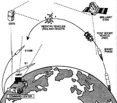
Source: Strategic Defense Initiative Organization,
1991 Report to the Congress on the Strategic Defense Initiative (May
1991), 2-7
Figure 6. GPALS Architecture: Ground-Based Protection
against Strategic Ballistic Missiles
For planning purposes, the ground-based defense tier of a GPALS system includes the following:
1. approximately 750 ground-based interceptors,2. six ground-based radars,
3. approximately 60 BE satellites, and
4. the appropriate command and control for the ground-based tier.80
If E2Is are used, BE would provide postboost and midcourse surveillance and GBRTs would support terminal intercepts. The BE satellite would track the PBVs, clusters of RVs, and, in some cases, individual RVs to provide the data to commit the E2I. The GBRT would acquire, track, and discriminate between RVs and decoys in the late midcourse and terminal portions of their trajectories, providing kill assessment and additional target selections to the E2I.81 If GBIs are used, either BE, GSTS, or some combination of each will be used to provide cluster tracks for the GBIs. GBIs may require GBRT for commitment against short time of flight SLBM, but this requirement remains to be validated as the program matures.82
The choice between E2I and GBI, or possibly whether to continue with both, will be made before full-scale development and will depend on the resolution of several issues at that time. Terminal defense could benefit from the easier discrimination of RVs from decoys by atmospheric slowdown, but only, at the expense of requiring a more complicated interceptor that could withstand the heating and mechanical stress caused by operating in the upper atmosphere. Midcourse interceptors are inherently simpler and could be used much more flexibly throughout the long midcourse portion of the RVs' flight trajectory. However, the defense must have confidence in its ability to discriminate RVs in midcourse in the expected threat environment.83
The same elements discussed above would counter SLBM attacks. The functions of the elements would be very similar to those performed in defending against ICBMs. This capability is shown in figure 7. However, an SLBM attack launched from a submarine very close to the US coast would constitute a more stressing threat, especially if flown on a depressed trajectory. Although BP would be effective against such an attack, those RVs not engaged by BP would have to be intercepted by ground-based interceptors to completely counter such an attack.84

Source: Strategic Defense Initiative Organization,
1991 Report to the Congress on the Strategic Defense Initiative (May
1991), 2-8
Figure 7. GPALS Architecture: Protection against SLBMs
The complete GPALS system is portrayed in figure 8. The effectiveness, survivability, and testability of this architecture are possible in large part because of the autonomy of its constituent parts.85

Source: Strategic Defense Initiative Organization,
1991 Report to the Congress on the Strategic Defense Initiative (May
1991), 2-9
Figure 8. Complete GPALS Architecture
The selection of an evolutionary path towards building and deploying the GPALS architecture is critical. In the future, more capable defenses will also require the selection of an evolutionary approach. This advanced defense capability depends heavily on how the threat may change, the mission desired, and the technologies available and their costs.86
The SDI program has examined a variety of concepts for advanced weapon and sensor elements, is developing the required technologies to support them, and has analyzed possible follow-on architectures. Preliminary observations suggest that if the US makes a decision to expand defense objectives beyond GPALS it could:
GPALS would add these two improvements, either sequentially or concurrently, to provide the capability to interactively discriminate RVs from decoys and other penetration aids during the midcourse phase of ballistic missile flight. They could also provide multiple capabilities to destroy boosters, PBVs, and RVs. Choices for missions, directed energy development timing, and directed energy types depend on the nature and timing of threat changes that require expansion beyond GPALS.87
Another promising element under investigation is the hypervelocity gun for situations that require high firepower. Also under study is the possibility of combining the inherent sensor capabilities of different weapon platforms. Such combinations could yield a more complete picture of the battle, thereby enhancing the effectiveness of the architecture and possibly reducing certain technical requirements for the weapons.88
1. "Space Operations Functions," vol. 10, course materials for ACSC (Maxwell AFB, Ala.: Air Command and Staff College, 1991), 60; and Lt Col Steve Malutich and Maj Jim Dill, "Space Support," vol. 10 (Maxwell AFB, Ala.: Air Command and Staff College, 1991), 61-64, 67.
2. Maj Theodore W. Burgner, "Space Handbook" (Paper presented as input for revision of Space Handbook, 45th Space Wing Operations Training Division, August 1991), 12.
3. Ibid., 14.
4. Ibid., 12.
5. Ibid., 13.
6. Ibid., 14.
7. Ibid., 12-14.
8. Ibid., 34-35.
9. Ibid., 16-18.
10. Ibid., 36-39.
11. Ibid., 23-29.
12. Ibid., 15.
13. Ibid., 18-20.
14. Ibid., 29-33.
15. Ibid., 22.
16. Ibid., 21.
17. Ibid.
18. AFM 1-6, Military Space Doctrine, 15 October 1982, 63.
19. Burgner, 44-45.
20. Ibid., 46.
21. Nicholas M. Short, The Landsat Tutorial Workbook (Washington, D.C.: NASA, 1982), 409.
22. House Committee on Science and Technology, Civil Land Remote Sensing System, 97th Cong., 1st sess., 1982, Committee Print, 9.
23. H. S. Chen, Space Remote Sensing Systems (San Diego, Calif.: Academic Press, Inc., 1985), 216.
24. Paul J. Curran, Principles of Remote Sensing (New York: Longman, 1985),141.
25. Short, 417.
26. Patricia A. Gilmartin, "France's Spot Satellite Images Helped U.S. Air Force Rehearse Gulf War Missions," Aviation Week & Space Technology, 1 July 1991, 22.
27. Ibid.
28. Burgner, 46.
29. Ibid., 48.
30. Ibid., 46 47.
31. James W. Canan, "Normalizing Space," in Space the Fourth Military Arena, ed. Connie Sessions and Gwen Story (Maxwell AFB, Ala.: Air University, 1992), 239.
32. AFM 1-1, Basic Aerospace Doctrine of the United States Air Force, vol. 1, March 1992, 9.
33. Ibid.
34. Capt Larry Jacks, "Space Surveillance Network," 1 SWG/DOOS paper, June 1991,1.
35. Ibid., 2.
36. Ibid.
37. Ibid., 3.
38. Ibid., 4.
39. Ibid., 5.
40. Ibid., 6.
41. Ibid., 7.
42. Ibid., 8.
43. Ibid., 8-9.
44. Ibid., 10.
45. Ibid.
46. Ibid., 11.
47. Maj Steven R. Petersen, Space Control and the Role of Antisatellite Weapons (Maxwell AFB, Ala.: Air University Press, May 1991), 63.
48. Ibid., 66-67.
49. Ibid., 67.
50. Ibid., 69-70.
51. Strategic Defense Initiative Organization, 1991 Report to the Congress on the Strategic Defense Initiative (May 1991), 2-1.
52. Ibid.
53. Ibid.
54. Ibid.
55. Ibid.
56. Ibid., 2-1, 2-2.
57. Ibid., 2-2.
58. Ibid.
59. Ibid., 1-1.
60. Ibid., 2-2.
61. Ibid., 1-4.
62. Ibid.
63. Ibid.
64. Ibid.
65. Strategic Defense Initiative Organization, The President 's New Focus for SDI: Global Protection against Limited Strikes (10 April 1991), 2.
66. SDIO, Report to Congress, 1-5.
67. Ibid.
68. Ibid., 1-7, 1-8.
69. Ibid., 1-8.
70. Ibid.
71. Ibid.
72. Ibid., 2-2.
73. Ibid., 2-3.
74. Ibid., 2-6.
75 . Ibid., 2-5 .
76. Ibid., 2-6.
77. Ibid.
78. Ibid.
79. Ibid.
80. Ibid.
81. Ibid.
82. Ibid.
83. Ibid., 2-7.
84. Ibid.
85. Ibid.. 2-8.
86. Ibid.
87. Ibid., 2-9.
88. Ibid., 2-10.