|
|||||||
|
Cryptome DVDs are offered by Cryptome. Donate $25 for two DVDs of the Cryptome 12-years collection of 46,000 files from June 1996 to June 2008 (~6.7 GB). Click Paypal or mail check/MO made out to John Young, 251 West 89th Street, New York, NY 10024. The collection includes all files of cryptome.org, jya.com, cartome.org, eyeball-series.org and iraq-kill-maim.org, and 23,000 (updated) pages of counter-intelligence dossiers declassified by the US Army Information and Security Command, dating from 1945 to 1985.The DVDs will be sent anywhere worldwide without extra cost. | ||||||
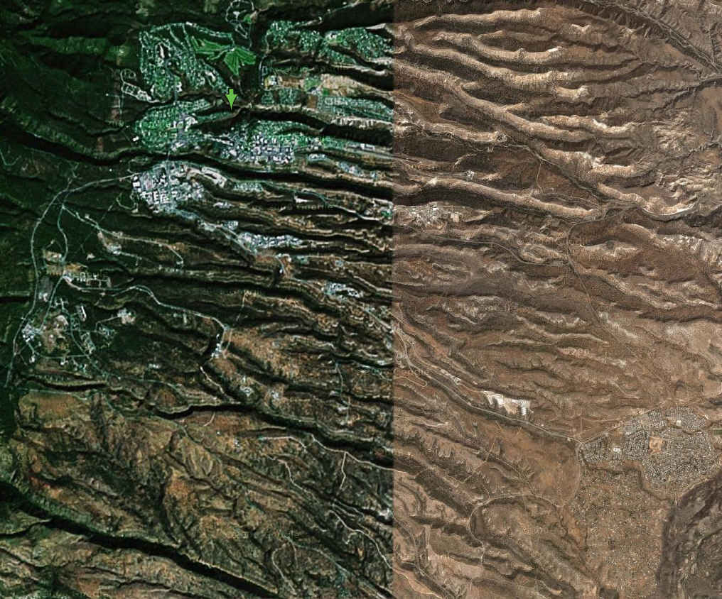
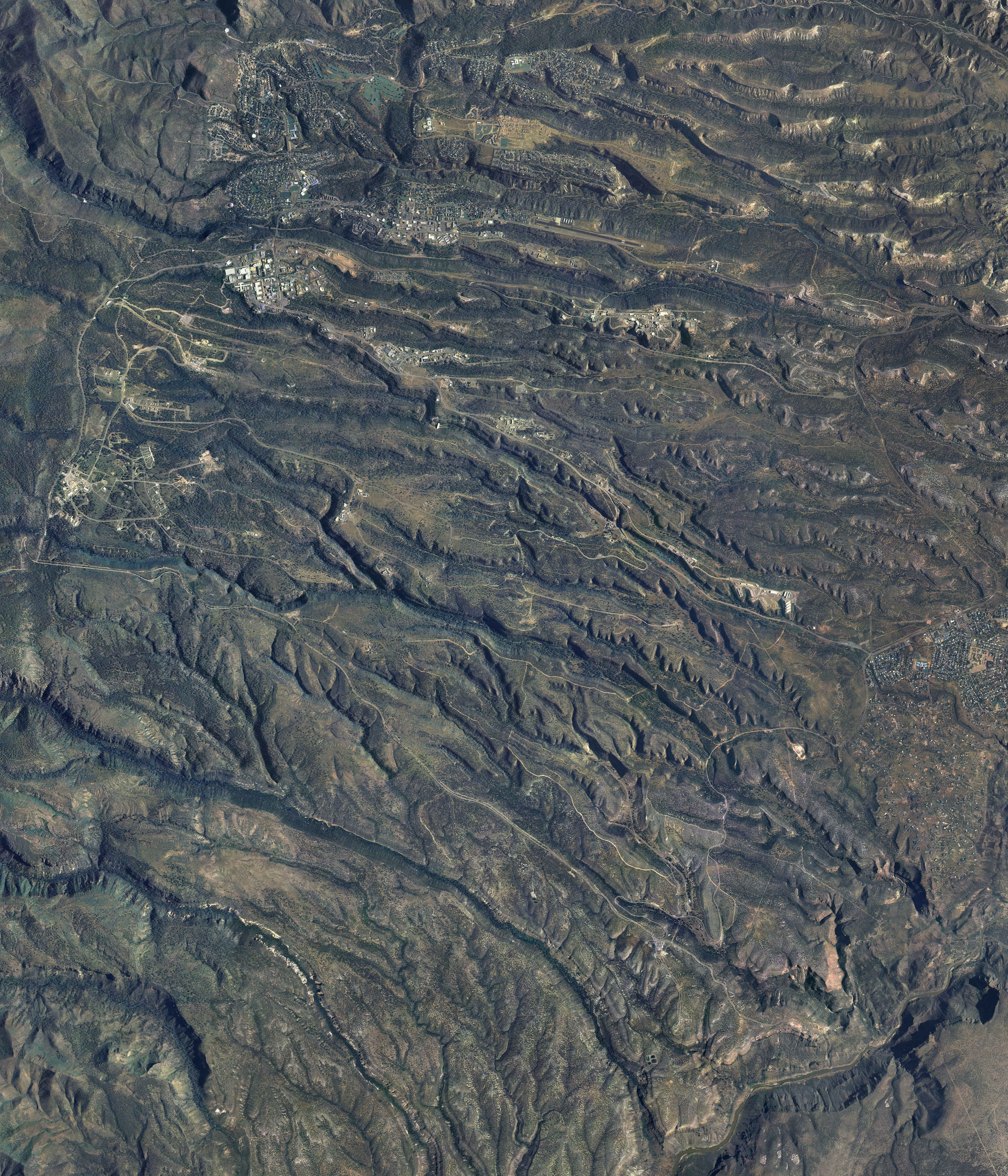
13 September 2006. Updated with 2005 digital orthographic photos from the State of New Mexico:
http://rgis.unm.edu/loader_div.cfm?new=true&theme=2005%20Digital%20Orthophotos
For aerial photos of LANL, located in Los Alamos County, select under "Extents Search" quarter-quads named:
Frijoles NE, NW, SE and SW
Guaje Mountain SE and SW,
Puye SW
White Rock NW and SW
There are no direct URLs for the files which are generated for download as a Zipped file in ECW format of 10-14MB.
A viewer for ECW files, "Irfan View 3.98:" http://www.irfanview.com/
Get the program and the plug-in. Once opened in Irfan View the files can be saved in a variety of graphic formats.
8 May 2004. One of the Eyeball series.
Maps from Mapquest.com
Source of aerial photos:
http://www.terraserver-usa.com
Los Alamos National Laboratory: http://www.lanl.gov
Wall Street Journal, May 7, 2004:
U.S. to Consolidate Nuclear Materials In Antiterror StepBy JOHN J. FIALKA
Staff Reporter of THE WALL STREET JOURNALWASHINGTON -- The Energy Department is expected to announce it will consolidate much of its excess nuclear-weapons material at a few highly protected sites, a move intended to improve security against potential terrorist attacks and save more than a $100 million in annual costs.
Elements of the plan have been discussed for weeks on Capitol Hill and among department scientists, some of whom oppose the policy on grounds that they need frequent access to bomb-grade metals -- highly enriched uranium and plutonium -- for research purposes. Governors of some states have also been consulted about the plan.
A department spokesmen wouldn't comment about details of the plan, except to say that Energy Secretary Spencer Abraham today will announce "major initiatives" to improve security at the nation's nuclear-weapons labs and several other facilities where such materials are known to be stored.
One of the concerns is the possibility that terrorists penetrating such facilities might quickly use conventional explosives with seized materials to create what is known as an "improvised nuclear device," a crude and dirty weapon that might have some nuclear explosive force.
The concerns have been heightened by "force-on-force exercises" involving Army special-forces teams to test security at Energy Department facilities. They have demonstrated several times at Los Alamos National Laboratory, for example, that quick attacks by small, well-trained teams can penetrate department security forces and gain access to simulated nuclear materials used in the exercises.
Scientists at the labs have asserted that they need access to nuclear-bomb metals to assess how nuclear weapons obtained by terrorists or rogue nations might work. They also need to study how the characteristics of plutonium -- an explosive metal that is used in most of the nation's nuclear warheads -- changes as it ages. Some of the research, however, can be simulated on computers.
Because the nation no longer tests nuclear weapons, one of its newest and most secure facilities is likely to become one of the consolidation points for the excess materials. It is called the Device Assembly Facility and is located at the Nevada Test Site, a remote, desert area north of Las Vegas where weapons were once tested underground.
Earlier, the Energy Department announced that it would begin a program to consolidate nuclear materials by removing them from a site at Los Alamos, where scientists used plates and blocks of plutonium and special reactors to model the nuclear potential of weapons.
According to the department, Mr. Abraham will spell out his new plan at a meeting of his agency's top security officers at the department's Savannah River Site, near Aiken, S.C. He is expected to say that his agency will build a new, highly secure site at Oak Ridge, Tenn., that will take over custody of large amounts of highly enriched uranium kept at a complex there called Y-12. Livermore National Laboratory in California is expected to be another site where "special nuclear materials" will be consolidated and eventually removed.
Danielle Brian, executive director of the Project on Government Oversight, a Washington-based group that has lobbied for improved security at the nuclear sites, said she was "guardedly optimistic" that Mr. Abraham will unveil a comprehensive security approach. Unchanged research and security practices, some dating from the Cold War, she said, have left "multiple targets, dilapidated infrastructure and very short timelines for the terrorists to reach their targets."
Write to John J. Fialka at john.fialka@wsj.com
Danielle Brian's Congressional testimony on the need for protecting Sensitive Nuclear Material (SNM) from terrorist attack:
http://www.pogo.org/p/environment/et-040401-nuclear.html
Text and maps of LANL Technical Areas holding SNM were excerpted from two LANL complete descriptions of its facilities dated March 1998:
http://www.atomictraveler.com/LANL-TechAreas1.pdf
Other descriptive documents are available at www.atomictraveler.com.
Technical Areas holding SNM March 1998:
TA-3
TA-16
TA-18
TA-21
TA-35
TA-55
|
| Google
Maps
|
 |
 |
 |
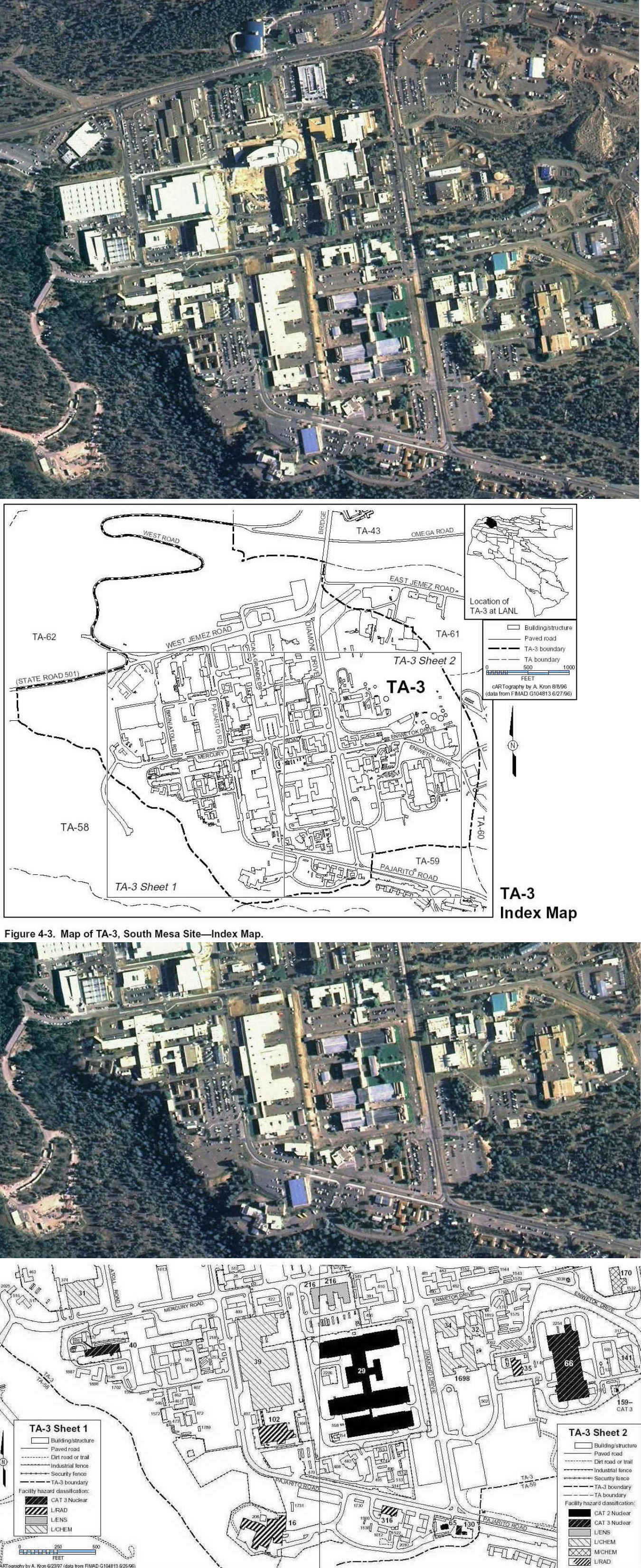
4.3.1 Site Description
TA-3 is the Laboratory’s main technical area [Table 4-3 and Figure 4-3 (index map for TA-3)], which houses approximately half of the Laboratory’s employees and contains about half of the total Laboratory floor space. It is the entry point to the Laboratory, and most of the administrative and public-access activities are located within its boundaries. The site also contains a mixture of the Laboratory’s activities, which include experimental sciences, SNM, administrative, public and corporate access, theoretical/computations, and physical support operations. Security requirements at TA-3 range from buildings open to the general public to buildings that have the strictest security. The latter buildings are provided with fences, guards, electronic surveillance, and other security measures, as necessary, and personnel must have appropriate security clearances to enter.
4.3.2 Facilities Description
The facilities at TA-3 are as varied as the activities. The Administration Building (Building 43) contains the Director’s Office, many of the offices of the Laboratory’s program directors, and the main auditorium (where classified and unclassified meetings are held). The Otowi Building (Building 261) contains the Human Resources Division offices, most Business Operations Division offices, and the main cafeteria. Other major office buildings located in this TA are the Sherwood Building (Building 105), the Syllac Building (Building 287, which contains a very large high-bay area that has been used as an experimental research area), the JCINNM Facilities Building (Building 38), and Buildings 28, 123, and 200. The main library, part of which is open to the public, is located in the J. Robert Oppenheimer Study Center (Building 207). The Laboratory’s major computing and data communications centers are located in Buildings 132 and 1498, respectively. These two facilities house some of the world’s largest and fastest computers, which are critical tools in meeting the scientific goals of the Laboratory’s assigned missions.
Many of the Laboratory’s major facilities for providing physical support in the form of utilities and maintenance are located in TA-3. Much like a university campus, research facilities are scattered throughout the area. These range from small laboratories with bench-scale operations to activities involving radioactive materials carried out in the CMR Facility (Building 29). Many of the TA-3 research facilities are described below.
4.3.2.1 Facility Hazard Categories
Table 4-3 identifies the facilities in TA-3 that fall into a facility hazard category because of the type of operations performed in the facility.
![[Image]](lanl-ta-03-t43.jpg)
4.3.2.1.1 Nuclear Facility Hazard Categories
Within the boundaries of TA-3, six facilities are currently categorized as nuclear facilities; two are categorized as Hazard Category 2, and four are categorized as Hazard Category 3.
4.3.2.1.1.1 Hazard Category 2 Nuclear Facilities
4.3.2.1.1.1.1 Chemistry and Metallurgy Research Facility
The CMR Building (Building 29, Figure 4-3, Sheet 2) was completed in the early 1950s to house research and experimental facilities for analytical chemistry, plutonium and uranium chemistry, and metallurgy, as well as some engineering design and support functions. In 1960, an addition (Wing 9) was constructed to support programs requiring hot-cell facilities.
The building is a three-story, reinforced-concrete structure that contains approximately 550,000 ft2 (167,640 m2) of floor space. The building has seven laboratory wings and one administration wing, all connected to a central (spinal) corridor. Each wing is designed to operate independently, and each has its own electrical power substation and ventilation system. The first floor of each laboratory wing contains approximately 48,000 ft2 (14,630 m2) of laboratory space and an equal amount of office space. The basement and second-floor spaces were designed to provide utility services for the first-floor laboratories and offices.
Wings 2, 3, 4, 5, and 7 extend from the spinal corridor and are identical in design and construction. Wings 6 and 8 were planned but never constructed. The main floor of each wing has change rooms at the entrance and offices along the outside walls. Two corridors separate the offices from laboratories. At the end of each wing are filter towers, which house the filter plenums and other large mechanical equipment for the exhaust ventilation system. Nuclear materials storage vaults are located on the main floors in Wings 2, 3, 4, 5, and 7. The basements of some wings house laboratory and office areas; the second floors of the wings are large, open areas with some building support equipment and storage areas.
Wings 1, 9, and the Administration Wing are unique. Wing 1 contains offices and inactive laboratories and does not have a filter tower. Wing 9 is a large bay area containing hot cells with remote handling capabilities and other support laboratories; men’s and women’s change rooms are located at the interior access to the wing. The Administration Wing houses offices and conference rooms.
The CMR Building was constructed to comply with the 1949 Uniform Building Code. The DOE has upgraded and maintained the facility over the years to ensure safe operation in support of programmatic missions. A major project is currently under way to further upgrade the facility.
Additional information regarding the upgrade project can be found in the Final Environmental Assessment for the Proposed CMR Building upgrades (DOE 1997a). The R&D tasks and other operations carried out in the building are varied; the types and numbers of projects change frequently and may involve nuclear materials. Projects take advantage of the special capabilities of the facility, including those involving safety, security, ventilation, and special processes. User organizations and specific tasks typically differ between from wing to wing and within wings.
The facility has housed analytical chemistry functions since it was constructed. Process chemistry and metallurgy R&D operations involving plutonium and other actinides have been performed continuously. These activities support many LANL and other DOE programs conducted primarily at other facilities, such as plutonium-processing and uranium-related activities.
Because many activities conducted in the building are potentially hazardous, controls and procedures have been adopted to protect workers from chemical, electrical, mechanical, and radioactive hazards. Hoods and gloveboxes are used in laboratories where chemical and radioactive materials are handled, and personnel are trained to use them safely. Other safety measures include restricted entry, hazard warning signs, protective clothing, and containerization of hazardous materials. Laboratory criticality safety personnel review areas that contain significant quantities of nuclear materials to identify safe operating limits.
CMR’s main vault is one of three Category 1 SNM storage vaults at the Laboratory available for nuclear material storage. This vault currently contains a variety of enriched-uranium materials, uranium feed material for manufacturing operations that occur in the Sigma Building, and samples from analytical chemistry operations. The use of the vault is not expected to change significantly in the future.
The term “Category 1 SNM storage vault” as used here does not refer to the hazard categorization process but to DOE’s designation of how much SNM a storage vault is authorized to hold based March 1998 2 4 TA and on its design and its ability to meet specific security requirements. Further information on this subject is provided in DOE Order 5633.3B, “Control & Accountability of Nuclear Materials” (DOE 1994a).
4.3.2.1.1.1.2 Sealed Source Building
The Sealed Source Building (Building 65, Figure 4-3, Sheet 2) is categorized as a Hazard Category 2 nuclear facility because it contains encapsulated radioactive materials and SNM used in health physics measurements research. This building is located inside a fenced area on the south side of Pajarito Road and Diamond Drive. The radioactive sources and SNM are sealed in steel containers, which are kept in a vault equipped with a steel door and combination lock. Only source custodians have access to the vault. The materials are used only inside appropriate shielding. The term “encapsulated” refers to radioactive material that is totally encased by a container. Encapsulation greatly reduces the likelihood that normal use will result in loss of radioactive material or dispersal. The emissions of the radioactive material are typically intended for continued or repetitive use as a known source of radiation for health physics measurements.
4.3.2.1.1.2 Hazard Category 3 Nuclear Facilities
4.3.2.1.1.2.1 Health Physics Instrumentation Calibration Facility
The Laboratory’s Health Physics Instrumentation Calibration Facility (West Wing, Building 40, Figure 4-3, Sheet 1), a controlled-access area, is located in the west wing of the Physics Building, which is the only part of this building designated as a Hazard Category 3 nuclear facility. The rest of the building is considered to have only hazards routinely encountered by members of the public involved in activities similar to those conducted in the Physics Building outside the west wing. The functions conducted in the calibration facility are calibrating and evaluating all types of radiation detection instrumentation used throughout the Laboratory. This instrumentation includes alpha, beta-gamma, neutron, and tritium gas detectors.
Calibrating the various radiation detection instruments requires using sources of radiation appropriate to the instrument. An instrument that measures alpha radiation needs to be calibrated against a source whose level of alpha radiation is known. In the descriptions that follow, the sources referred to are these sources of known radiation.
Three operating laboratories (W-4, W-120/120-A, and W-10) and two radioactive material source storage vaults (W-133 and W-8B) in the west wing support this activity. Two of the laboratories are used for calibrating and evaluating radiation detection instruments and detectors. The third laboratory is used to determine neutron emission rates from neutron sources. Only one of the storage vaults (W-133) is authorized to store sources containing SNM.
W-120/120A and W-133 are located on the first floor of the west wing. W-120 is approximately 200 ft2 (61 m2) and is constructed of both reinforced concrete and concrete block. W-120A is a metal-fabricated structure in W-120 that contains the actual calibration range. The range consists of tubes constructed of steel encased in concrete, which are used to house the various radioactive calibration sources.
W-133, a storage vault of approximately 160 ft2 (49 m2), is constructed of reinforced concrete and contains radioactive material transfer containers and metal cabinets. Steel tubes inserted in the concrete floor of the vault for source storage occupy most of the floor space.
W-4, W-8B, and W-10 are located in the basement of the west wing. Access to these rooms is by elevator or stairwell. All of the rooms are constructed of reinforced concrete. W-4 is a laboratory used primarily for calibrating neutron-emitting sources for determining neutron emissions. W-8B, the other vault, is a secondary radioactive materials storage vault in which radioactive materials used in W-4 and W-10 are stored. No SNM storage is authorized for this vault. W-10 is used for calibrating tritium instrumentation. This room is equipped with a laboratory fume hood in case tritium is released during calibration.
4.3.2.1.1.2.2 Sigma Complex
The Sigma Building (Building 66, Figure 4-3, Sheet 2) and three other main buildings [Building 35 (Press Building), Building 141 (Rolling Mill Building), and Building 159 (Thorium Storage Building)] make up the Sigma Complex, which is enclosed by a security fence and to which access is controlled by a guard station. The complex, which encompasses over 200,000 ft2 (60,960 m2), was constructed in increments during the 1950s and 1960s and has been used for a variety of nuclear materials missions. Today, the facility is primarily used for synthesizing materials and for processing, characterizing, and fabricating metallic and ceramic items, including items made of depleted uranium (DU). In the past, Sigma Complex processed all isotopes of uranium; therefore, much of the equipment is radioactively contaminated at very low levels. Nonradioactive hazardous materials used included a number of chemicals and metals such as beryllium.
The Sigma Building is categorized as a Hazard Category 3 nuclear facility. Constructed in 1958 and 1959, the building has approximately 168,200 ft2 (51,267 m2) of floor space spread over 4 levels. Most of the space is occupied by laboratories for metallurgical and ceramics projects, offices and administrative space, and storage areas for hazardous chemicals (such as concentrated acids and caustic solutions). The rest of the space, about 55,000 ft2 (16,764 m2), is devoted to various mechanical systems that provide for ventilation and other equipment required for protecting the facility and workers. Building and process air is exhausted from the building through five major stacks and numerous small roof stacks.
Today, the Sigma Building is primarily used for materials synthesis and for processing and characterizing and fabricating metallic and ceramic items, including DU items used in the Stockpile Stewardship and Management Program. Bulk DU is stored in the Sigma Building as supply and feed stock. Current activities in the Sigma Building focus on test hardware, prototype fabrication, and materials research for the DOE’s Nuclear Weapons Program, but they also include activities related to energy, environment, industrial competitiveness, and strategic research.
Information on the rest of the Sigma Complex can be found in Section 4.3.2.1.2.2.2, Press Building; Section 4.3.2.1.2.4.5, The Rolling Mill Building; and Section 4.3.2.1.1.2.4, Thorium Storage Building.
4.3.2.1.1.2.3 Calibration Building
The Calibration Building (Building 130, Figure 4-3, Sheet 2) is categorized as a Hazard Category 3 nuclear facility because it contains radioactive sources. The sources are used to calibrate instruments for evaluating the response of various detectors to x-ray, gamma, beta, and neutron emissions.
The building is made up of two structures—the main building and an annex attached to its southeast end. It is located inside the same fenced area as the Sealed Source Building (Section 4.3.2.1.1.1.2).
To prevent contamination of facility workers under normal operating conditions, all radioactive sources and SNM are encapsulated or sealed in containers, including during the time they are being used for instrument evaluations. (No processing of nuclear material takes place in the Calibration Building.) Only Laboratory research staff and designated custodians handle the radioactive sources and SNM.
4.3.2.1.1.2.4 Thorium Storage Building
The Thorium Storage Building (Building 159, Figure 4-3, Sheet 2), part of the Sigma Complex (Section 4.3.2.1.1.2.2), is a Hazard Category 3 nuclear facility because it is used for storing thorium in both ingot and oxide forms. To ensure material accountability and to limit radiation doses to personnel, Building 159 is surrounded by fencing and has its own controlled access.
4.3.2.1.2 Non-Nuclear Facility Hazard Categories
Within the boundaries of TA-3 are one M/CHEM facility, four L/RAD facilities, one L/ENS facility, and eight L/CHEM facilities.
4.3.2.1.2.1 Building Categorized M/CHEM
The Liquid and Compressed Gas Facility (Building 170, Figure 4-3, Sheet 2) is the Laboratory’s receiving and distribution point for bulk quantities of specialized gases used in R&D activities. Cylinders of various sizes, as well as trailers, are staged at this facility.
4.3.2.1.2.2 Buildings Categorized L/RAD
4.3.2.1.2.2.1 Ion Beam Building
The Ion Beam Building (Building 16, Figure 4-3, Sheet 1) consists of approximately 58,000 ft2 (17, 678 m2) of usable space. The building houses an accelerator capable of energies from 250 keV to 150 MeV, which can provide pulsed ion beams to 0.5 ns. The accelerator is capable of accelerating microparticles at >62 mi/s (>100 km/s). The facility is currently in safe-shutdown mode. All sources have been removed. Current plans are to convert the entire building to office space.
4.3.2.1.2.2.2 Press Building
The Press Building (Building 35, Figure 4-3, Sheet 2), built in 1953, is part of the Sigma Complex. It contains approximately 9,860 ft2 (3,005 m2) of space on one floor and a partial basement. The only activity there is the operation of a 5,000-ton (4,536,000-kg) hydraulic press used for work with DU.
4.3.2.1.2.2.3 The Tech Shops Addition
The Tech Shops Addition, also called the Uranium Shop (Building 102, Figure 4-3, Sheet 1), was constructed in 1957 and consists of approximately 23,000 ft2 (7,010 m2), including a 125-ft- (38-m-) long corridor that connects it with the main shops (Section 4.3.2.1.2.4.4). Its construction is similar to that of the main shops. The building houses the uranium shop, which is ventilated through a portable high-efficiency particulate air (HEPA) filtration system. This facility, like the main shops, contains a variety of metal-forming machines. Although DU represents the bulk of the materials used in parts fabrication, many other potentially hazardous materials are used in this facility.
4.3.2.1.2.2.4 High-Voltage-Test Facility
Physics research is conducted in the High-Voltage-Test Facility (Building 316, Figure 4-3, Sheet 2). Current activities at this facility are below threshold levels for the L/RAD category. Past activities at the facility exceeded the threshold.
4.3.2.1.2.3 Building Categorized L/ENS
4.3.2.1.2.3.1 The Weapons Test Support Facility
The Weapons Test Support Facility (Building 216, Figure 4-3, Sheets 1 and 2) is a physics research and design facility. All research using lasers and x-rays is conducted in shielded areas in accordance with standard operating procedures.
4.3.2.1.2.4 Buildings Categorized L/CHEM
Several of the buildings below categorized as L/CHEM represent significant Laboratory resources and are therefore described in some detail.
4.3.2.1.2.4.1 Water Treatment House
The Water Treatment House (Building 24, Figure 4-3, Sheet 2) contains a gas chlorination unit. It is used to treat cooling tower water during the production of steam at the TA-3 Steam Plant (Building 22).
4.3.2.1.2.4.2 Warehouses
The Laboratory’s main general warehouse (Building 30) and chemical warehouse (Building 31, Figure 4-3, Sheet 1), both of which can store limited quantities of hazardous chemicals, are categorized L/CHEM. The chemical warehouse is managed by a subcontractor.
4.3.2.1.2.4.3 Laboratories
Building 32, the Center for Material Science (also called the Cryogenics Building A), and Building 34, the Cryogenics Building B (also called the Condensed Matter and Thermal Physics Laboratory) (Figure 4-3, Sheet 2), are used for materials research. Although Building 32 is known as the Center for Material Science (Figure 4-3, Sheet 2), the building is one of several that serve a Laboratory program focusing on material sciences [e.g., Buildings 32 and 34, and the Materials Science Laboratory (MSL) (Building 1698, Section 4.3.2.1.2.4.6)]. Scientists at the center are involved in developing and bringing material science work to the Laboratory. Building 32, used for cryogenics research, uses liquid nitrogen. Building 34’s ground-floor laboratories are used for condensed matter and thermal physics research. Downstairs is the Ion Beam Materials Laboratory. Although the rest of Building 34 is categorized L/CHEM, the Ion Beam Materials Laboratory is categorized L/ENS.
4.3.2.1.2.4.4 The Tech Shops
LANL’s main shops (Building 39, Figure 4-3, Sheet 1) are located in the southwestern quadrant of TA-3. The shops consist of two buildings—the main shops in Building 39 and the Tech Shops Addition (also called the Uranium Shop) in Building 102. Building 39 is constructed of poured concrete and cinder block and has a flat tar/gravel roof. The approximately 138,000-ft2 (42,062-m2) building, including a 13,500-ft2 (4,115-m2) administrative office area, was constructed in 1953. The building contains a variety of lathes, mills, and other metal-forming equipment. Building 39 also houses the beryllium shop (not limited to beryllium), which is ventilated through a HEPA filtration system. Although small, selected areas of the building are air-conditioned to provide an environment that allows parts to be fabricated accurately, most of the building space is not air-conditioned. Other small areas with special ventilation include painting, welding, and grinding areas.
4.3.2.1.2.4.5 The Rolling Mill Building
The Rolling Mill Building (Building 141, Figure 4-3, Sheet 2), which was built in the early 1960s and is part of the Sigma Complex, is categorized as L/CHEM. Its three levels encompass approximately 20,213 ft2 (6,161 m2) of space that houses powder metallurgy activities, filament welding, ceramics research and development, rapid-solidification research, and work with beryllium and uranium/graphite fuels. The beryllium area has a permitted, monitored stack equipped with a HEPA filter. Rooms 142, 148, 150, and 144 are vented through a bag-filtered exhaust system designed to remove carbon and graphite dust. The other parts of the building are vented through unfiltered vents and stacks.
4.3.2.1.2.4.6 The Materials Science Laboratory
The Materials Science Laboratory (Building 1698, Figure 4-3, Sheet 2) is used for processing materials, studying mechanical behavior in extreme environments, developing advanced materials, and characterizing materials. The MSL is bounded on the west by Diamond Drive, on the north by Buildings 32 and 34 (Section 4.2.3.1.2.4.3), on the east by the security fencing that surrounds the Sigma Complex (Section 4.3.2.1.1.2.2), and on the south by Pajarito Road. The MSL building and its corresponding access roads, parking lots, and landscape areas cover a site of approximately 7 acres (2.8 ha).
This facility is a two-story laboratory of approximately 55,360 ft2 (16,874 m2) arranged in the shape of an H. The MSL is constructed of precast concrete panels sealed to a structural steel framework, concrete floors, drywall interior, casework, hoods, and a utility infrastructure. Safety controls throughout the building include a wet-pipe sprinkler system; automatic fire alarms; chemical fume hoods; gloveboxes; HEPA-filtered heating, ventilation, and air conditioning (HVAC); and safety showers.
MSL contains 27 laboratories and 21 distinct materials research areas, which can be categorized as 4 major materials science experimental areas: materials processing, mechanical behavior in extreme environments, advanced materials development, and materials characterization. These 4 areas contain over 20 operational capabilities that support materials research activities related to energy, environment, nuclear weapons, and industrial competitiveness. In addition, the facility contains 60 offices; 15 support rooms; and conference rooms used by technical staff, visiting scientists and engineers, administrative staff, and building support personnel.
The first floor contains a high bay and materials characterization and processing laboratories in the east wing; materials synthesis, characterization, and processing laboratories in the west wing; and administrative and personnel interaction areas in the center. The second floor contains computer rooms in the east wing; additional materials synthesis, characterization, and processing laboratories in the west wing; and building services and additional personnel interaction areas in the center. Small offices are located along the exterior walls throughout most of the building.
Appropriate safety systems are designed into the building for those laboratories in which potentially hazardous activities occur. These systems include detection systems, warning lights, physical barriers, and appropriate exhaust ventilation systems. The building is configured so that service corridors connect the laboratories, allowing materials to be transported, stored, and used in a ventilation zone separated from pedestrian corridors and staff offices. Some of the laboratories are provided with special features such as vibration isolation, electromagnetic shielding, and HEPA filters. All laboratories contain a variable-air-volume ventilation system, as well as process cooling water, large-capacity electrical circuits, and vacuum pump exhaust systems. The exhaust ventilation system is provided with an automated alarm system to indicate offnormal conditions. The MSL was designed to accommodate a wide variety of chemicals used in small amounts that are typical of many university and industrial materials research facilities. Some of these chemicals are hazardous, toxic, and/or radioactive. The various laboratories in MSL produce four liquid wastes: (1) sanitary, (2) acid/caustic, (3) nonflammable organic, and (4) flammable organic. The MSL is located in an unsecured area adjacent to secured facilities that house most of the Laboratory’s materials scientists and engineers. The building is not a production facility but a facility dedicated to the types of materials research conducted in a university and in industry.
4.3.2.2 Nonhazardous Facilities
Three hundred sixty-six administrative, technical, physical support, and other buildings and structures at TA-3 (Figure 4-3) contain operations that are not considered to involve unusual hazards. Some of the major nonhazardous facilities contained in TA-3 are the Laboratory’s main office building (Building 43), which contains the Director’s Office, most of the offices of the Laboratory’s program directors, and the main auditorium. The Otowi Building (Building 261) houses the Human Resources (HR) Division offices, as well as the main cafeteria. Other major office buildings located in this area are the Sherwood Building (Building 105), the Syllac Building (Building 287), the Laboratory Support Contractor Building (Building 38), and Buildings 28, 123, 200, and 410. The Laboratory’s major computing and data communications centers are located in Buildings 132 and 1498, respectively. The main library is located in the J. Robert Oppenheimer Study Center (Building 207). The Wellness Center (Building 1663), Fire Station #1 (Building 41), and the Occupational Medicine Facility (Building 409) are also located at TA-3.
Several of the Laboratory’s major facilities for utilities and general grounds upkeep are located in TA-3. Steam required for operations is provided by the steam plant (Building 22). The Laboratory’s utility control center and main substation are located in Buildings 223 and 233, respectively.
The Parks and Refuse Office is located in Building 70. Other important structures located at TA-3 include switch-gear stations (Buildings 23 and 1682), cooling towers (Buildings 25 and 58), and the asphalt concrete plant (Building 173).

4.11.1 Site Description
TA-16 [Table 4-9 and Figure 4-11 (index map of TA-16)] is the location of extensive HE facilities and the Laboratory’s state-of-the-art tritium facility. HE activities that take place at TA-16 are developing and testing HE, plastics, and adhesives and conducting research in process development for manufacturing items that use these and other materials. Tritium activities include repackaging tritium, chemical purification of 3He, mixing tritium with other gases, analyzing gas mixtures, repackaging tritium to user-specified pressures, reclaiming tritium, and conducting applied R&D for boost systems.
4.11.2 Facilities Description
Seventy-eight HE-processing buildings at TA-16 provide 280,000 ft2 (85,344 m2) of space. The research, development, and testing capabilities provided at these facilities include large-scale HE processing; manufacturing HE powders; casting, machining, and pressing HE components; inspection and radiography of HE components to guarantee integrity and ensure quality control for design intent; hydrotesting and assembling test devices; and chemical analysis of HE. Some of these buildings are used for storing SNM and for storing, treating, and disposing of HE. Two buildings are currently being used for tritium operations. An additional building is being modified for tritium work at TA-16.
4.11.2.1 Facility Hazard Categories
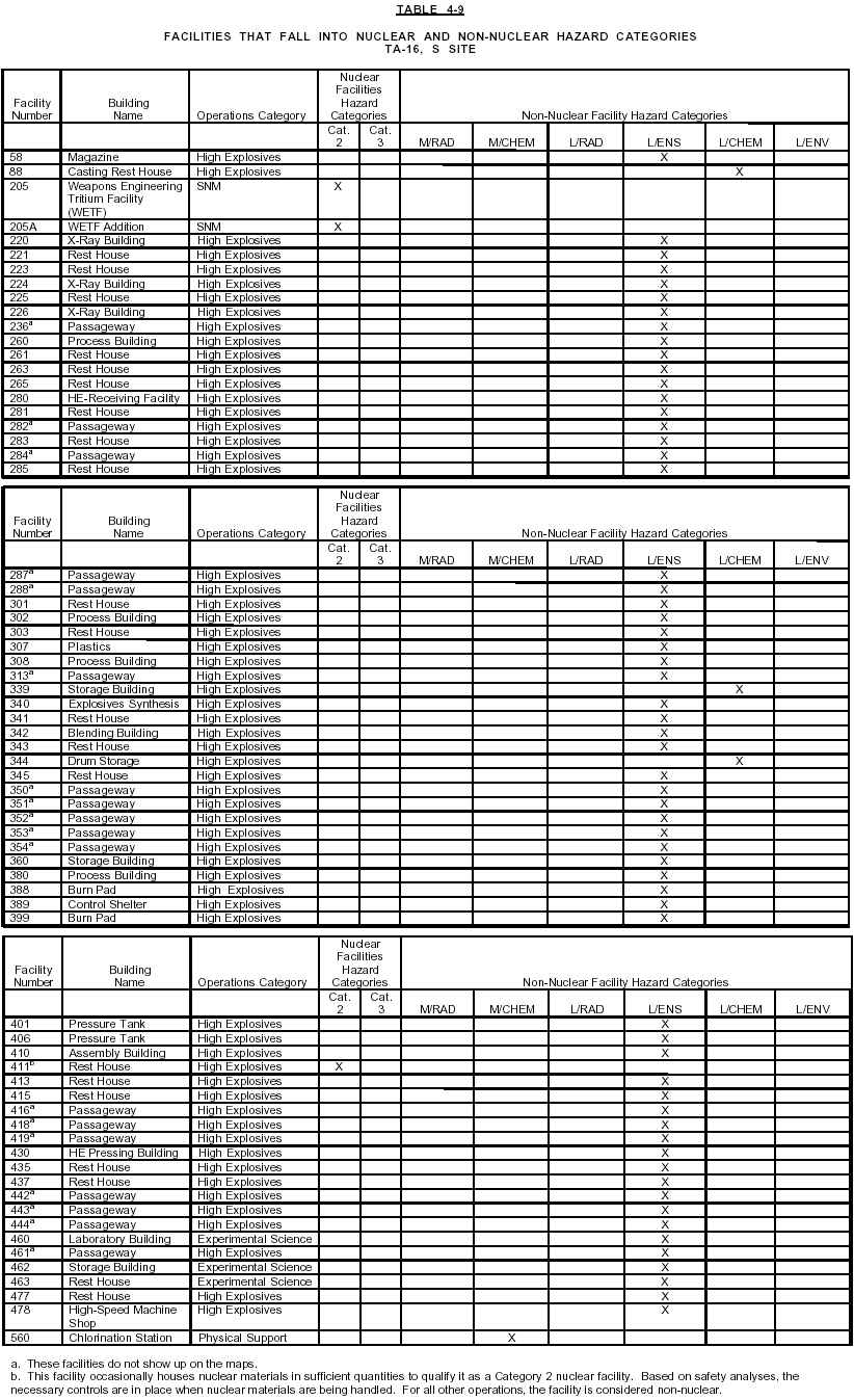
Table 4-9 identifies the facilities at TA-16 that fall into a facility hazard category because of the type of operations performed in the facility.
4.11.2.1.1 Nuclear Facility Hazard Categories
4.11.2.1.1.1 Hazard Category 2 Nuclear Facilities
TA-16 contains two Hazard Category 2 nuclear facilities: the Weapons Engineering Tritium Facility (WETF) (Buildings 205 and 205A; Figure 4-11, Sheet 2) and the Rest House (Building 411).
4.11.2.1.1.1.1 Weapons Engineering Tritium Facility
WETF is located in Buildings 205 and 205A in the southeast section of TA-16 outside the explosives area. WETF is in a secured area patrolled by armed guards. Building 205 is specifically designed and built to process tritium safely and to meet user needs and specifications. Planning for WETF began in 1981 to replace an aging tritium-processing facility located at TA-33. Construction began in 1982 and was completed in 1984. The operational readiness review of WETF was performed by DOE-Albuquerque in three phases, which corresponded to various systems being ready for use. Phases I and II were completed in 1987, and Phase III was completed in 1988. WETF began operation in 1989.
Current DOE-approved operational safety requirements (OSRs) limit to 100 g the total “at-risk” tritium inventory in the facility at any given time. The OSRs define the at-risk inventory as that portion of the tritium inventory not in a secondary confinement vessel that would mitigate a release if the primary confinement vessel were compromised. The purpose of this limit is minimizing the source term for potential release during an event that could lead to a credible accident while providing the necessary flexibility for processing tritium. The quantity of tritium that can be stored in approved storage containers providing secondary confinement is unlimited; however, the area available for storing tritium containers is small.
Building 205 is a single-level structure except for a mezzanine area. The structure consists of reinforced, cemented, mortar unit walls set on reinforced-concrete footings. The walls are also reinforced at corners, joints, windows, and doors. The foundation is reinforced-concrete floor slab set on compacted fill. A precast, prestressed concrete, double T-beam roof is supported by reinforced concrete beams, columns, and cemented mortar unit walls.
An exterior steel stairway located at the west wall of Building 205A, an addition to Building 205, provides access to the roof. Effluents from the ventilation and cleanup systems in the tritiumhandling areas are exhausted through a 60-ft- (18-m-) high steel stack mounted on a concrete base. WETF has six entrances/exits and three exterior windows located in the two offices of Building 205. The total floor area is approximately 7,885 ft2 (2,403 m2) and is divided into multiple areas that include the control room, the tritium-handling areas, and the support areas.
Wall partitions and doors divide the tritium-handling areas into five rooms that contain the equipment used to handle and process tritium. Tritium may also be stored in containers in these rooms. Tritium-handling areas are separated from the rest of the facility by walls, doors, windows, air locks, and a zoned ventilation system. Personnel access to the radiologically controlled area is controlled through an air lock entry located at the control room. There is a staging area for shipments entering or leaving the tritium-handling area. The exterior metal doors to this area can only be opened from the interior and are used to provide access to the exterior loading dock during shipping and receiving.
Shipments containing tritium are admitted to WETF through a staging room that functions as a shipping and receiving area. Once receiving activities are complete, an item is moved into the tritium-handling area, where it is unpackaged. Unpackaging involves removing shipping containers from their protective overpacks and checking for leaks. If the contents are destined for processing by the tritium-gas-handling system (TGHS), the container is connected to the TGHS, and the required tritium-processing manipulations are performed by the TGHS equipment. At the completion of the processing activity, the tritium is off-loaded into an appropriate container, sealed, and then disconnected from the TGHS. Tritium may also be temporarily stored in vessels connected to the TGHS or in a metal hydride bed, known as a getter bed.
These areas are monitored for tritium and are controlled to a slightly negative pressure relative to atmosphere by a dedicated once-through ventilation system that exhausts to a 60-ft (18-m) stack. A separate ventilation system maintains the control room, which is also monitored for tritium, at a positive pressure relative to atmosphere and within a temperature range for proper operation of electronic equipment in the room. The control room is the operations focus for activities that monitor, control, and operate the facility systems. The control room is entered from the main entry foyer and is separated from the tritium-handling areas by walls, windows, and an air lock.
Construction of Building 205A started in 1993 and was completed in 1994. The addition was designed and built to provide more space for the same type of activities performed in the original building.
The operations at WETF are divided into two categories: tritium processing and activities that support tritium processing. Operations at WETF are described briefly in the following paragraphs. Tritium-processing operations include
• repackaging tritium into smaller quantities,• removing the 3He decay product and other contaminants,
• mixing tritium with other gases,
• analyzing gaseous tritium and gas mixtures,
• repackaging tritium and other gases to user-specified pressures,
• performing various user-defined experiments that use tritium,
• unloading containers of tritium,
• performing function tests of components and apparatus containing tritium,
• reacting tritium with other materials to form compounds,
• fusion target and neutron tube target loading, and
• analyzing the effects of tritium.
WETF is designed to process tritium in quantities consistent with present and anticipated future needs while providing reliability and protection for workers, the public, and the environment. The tritium-processing activities occur in the tritium-handling areas and are typically performed in a TGHS, which is enclosed in glove boxes. The TGHS contains a variety of components that users require for manipulating tritium. Gloveboxes may stand alone or be joined together to form a glovebox line.
An inert atmosphere (typically nitrogen gas) in the gloveboxes reduces the potential for fire and for formation of tritium oxide, should tritium be released to a glovebox. The oxygen concentration in the glovebox is monitored and controlled through the facility computer system. The oxygen and hydrogen content of the tritium waste treatment system low-pressure receiver is also monitored and controlled to prevent flammable concentrations from accumulating. Fire protection (suppression and detection) in the facility consists of a full-coverage wet-pipe sprinkler network, fire detection devices, alarms, and pull stations. The control room has the additional protection of a Halon system.
To reduce the potential for inadvertent release, most processes, experiments, and storage configurations involving tritium typically use double containment. Operations in the TGHS components that provide primary confinement are housed in gloveboxes that provide secondary confinement. TGHS piping outside of gloveboxes is enclosed in a large-diameter pipe that provides secondary confinement for the tritium. Most tritium storage configurations include both a primary and secondary confinement barrier. The facility building structure, along with the ventilation isolation, forms the outermost confinement barrier against any tritium releases.
Strategically located tritium monitors provide computer signals and alert workers of tritium release concentrations above alarm set-point values. Each glovebox has a tritium monitor that initiates tritium gas cleanup system (TGCS) actions when a set point is exceeded. Room tritium monitors in the tritium-handling areas and in the control room and a tritium stack monitor alert workers of released tritium through alarms and other indicators. The stack monitor provides backup for the room monitors in the tritium-handling areas and monitors process effluents that are routed directly to the stack. These effluents are also monitored in the emergency tritium cleanup system and tritium waste treatment system before being routed to the stack. When certain alarm set points are exceeded, the tritium room monitors and stack monitor also initiate signals that lead to isolating the ventilation systems of the tritium-handling areas and sound the evacuation alarm. Tritium released to the tritium-handling areas is either cleaned up by the emergency tritium cleanup system before discharge through the stack or is discharged directly to the atmosphere through the stack in a manner that allows for a controlled release so as not to exceed allowable limits, as appropriate.
4.11.2.1.1.1.2 Rest House
A number of buildings in TA-16 are referred to as rest houses. The term “rest house” basically refers to a safe place to temporarily store something until needed. Building 411 (Figure 4-11, Sheet 2), along with Building 410 (Section 4.11.2.1.3.8), is used for assembling devices. Building 411 is occasionally used to warehouse nuclear material and classified parts in sufficient quantities to qualify it as a Category 2 nuclear facility. On these occasions, the building is considered to be a Hazard Category 2 nuclear facility. Based on safety analyses, the necessary controls are in place when nuclear materials are being handled. For all other operations, the building is considered non-nuclear. Many of the remaining rest houses at TA-16 are used as explosives magazines.
4.11.2.1.2 Non-Nuclear Facility Hazard Categories
4.11.2.1.2.1 Building Categorized M/CHEM
Building 560 (Figure 4-11, Sheet 2) houses a drinking water chlorination station.
4.11.2.1.3 Buildings Categorized L/ENS
Sixty-one facilities located in TA-16 are categorized L/ENS. Eighteen of the buildings identified in Table 4-9 as L/ENS are passageways between facilities. These passageways are not shown on Figure 4-11, nor are they discussed below. The descriptions below identify some building numbers that do not show on the maps. These structures do not currently have a hazard category.
4.11.2.1.3.1 Large-Scale Explosives Formulation and Fabrication Plant
The Large-Scale Explosives Formulation and Fabrication Plant (Buildings 58, 340-343, and 345; Figure 4-11, Sheets 2 and 3) has large-scale, HE-processing capabilities for manufacturing and processing HE powders, micronizing HE powders, pressing formulated powders into structured pieces, performing strength-of-materials testing on HE components, and conducting loading operations for some specialty explosives. Some small, special-test devices are also assembled here.
4.11.2.1.3.2 High-Explosives Inspection and Component Radiography
In the high-explosives inspection and component radiography facilities (Buildings 220, 221, 223-226, 280, 281, 283, and 285; Figure 4-11, Sheets 2 and 3), HE is inspected and components undergo radiography as part of the quality control process to guarantee integrity for design intent. Quality assurance includes using coordinate-measuring equipment and industrial x-ray devices to obtain dimensional and density measurements of HE components and test devices. Radiography takes place in Building 220; however, radiography operations will be consolidated and relocated in Building 260.
4.11.2.1.3.3 High-Explosives Fabrication
The high-explosives fabrication facilities (Buildings 260, 261, 263, 265, 301, 302, 380, 430, 435, and 437; Figure 4-11, Sheets 2 and 3) house HE fabrication processes. Machined components needed for weapons research and development and full weapons test assemblies are fabricated to specifications. Casting operations provide cast HE components for testing, as well as mock HE to be used in weapons systems training and in tests that use mockups of components as substitutes for actual HE components. HE-pressing operations consolidate plastic-bonded explosives into solid charges and into stock pieces for machining components for hydrotests and other HE testing.
4.11.2.1.3.4 Rest House
The rest house (Building 303; Figure 4-11, Sheet 3) is used for HE environmental testing.
4.11.2.1.3.5 Plastics Operations
Buildings 307 and 308 (Figure 4-11, Sheet 3) house plastics operations.
4.11.2.1.3.6 High-Explosives Receiving and Storage
To comply with DoD and DOE regulations, all HE and energetic materials shipped to the Laboratory must be received at the HE-Receiving Facility (Building 280, Figure 4-11, Sheet 2). Buildings 281-285 (Figure 4-11, Sheets 2 and 3) are used as magazines that store bulk HE and some limited HE components until they are needed for future processing.
4.11.2.1.3.7 High-Explosives Disposal and Treatment
The High-Explosives Disposal and Treatment Facility (Buildings 388-389, 399, 401, and 406; Figure 4-11, Sheet 3) disposes of HE and HE-contaminated wastes generated at the Laboratory. Current disposal techniques include open-air burning for solid HE and incineration for combustible HE-contaminated waste. HE-contaminated water, solvents, and oil are also treated in this processing area. All treated effluent is sampled and analyzed to be sure that it meets regulatory requirements. Buildings 399, 401, and 406 are not really buildings—Building 399 is a burn pad for disposal of HE, and Buildings 401 and 406 are sand filter vessels.
4.11.2.1.3.8 Test Device Assembly
Local hydrotesting and pre-Nevada-Test-Site device assembly are performed in Buildings 410 (Figure 4-11, Sheet 3) and 411 (Figure 4-11, Sheet 2). The facility has two large walk-in vaults that sometimes warehouse nuclear material and classified parts. Building 411 can also be used for SNM storage when extra security is provided, and Building 410 can accommodate a safe secure transport overnight. Buildings 413-415 are used as staging magazines.
4.11.2.1.3.9 Explosives Analytical Chemistry
The explosives analytical chemistry buildings (Buildings 460, 462, and 463; Figure 4-11, Sheet 2) are currently being used by the Laboratory’s biochemistry group rather than for explosives analytical chemistry. They are included here to identify their current use.
4.11.2.1.3.10 Laboratory Building/Rest House
This facility (Building 477, Figure 4-11, Sheet 3) is used for HE storage.
4.11.2.1.3.11 High-Speed Machine Shop
The high-speed machine shop (Building 478, Figure 4-11, Sheet 3) is used for remote HE machining.
4.11.2.1.4 Buildings Categorized L/CHEM
Three buildings in TA-16 are categorized as L/CHEM.
4.11.2.1.4.1 Casting Rest House
Building 88, also called the Casting Rest House (Figure 4-11, Sheet 2), currently houses a “museum” containing several previously tested mock weapons assemblies. Although no HE or HE operations are conducted in the building, it does contain depleted uranium, beryllium, and other weapons materials.
4.11.2.1.4.2 Storage Building
Flammable materials are stored in Building 339 (Figure 4-11, Sheet 3).
4.11.2.1.4.3 Drum Storage
Flammable materials are stored in Building 344 (Figure 4-11, Sheet 3).
4.11.2.2 Nonhazardous Facilities
A number of administrative/technical and physical support activities that do not involve any unusual hazards are located in various buildings at TA-16.

4.12.1 Site Description
TA-18 [Table 4-10 and Figure 4-12 (index map of TA-18)] is located in an arid canyon (Pajarito Canyon) about 4 mi (6.4 km) southeast of TA-3 on a DOE-owned and -controlled roadway (Pajarito Road). This roadway is normally open to the public but may be closed while hazardous materials are being moved or for other security or safety reasons. TA-18 is referred to as the Los Alamos Critical Experiments Facility (LACEF). It is also known as Pajarito Laboratory or Pajarito Site. The TA is a restricted area surrounded by a security fence with several additional layers of security and safeguards.
LACEF, which has operated since 1946, is the last general-purpose nuclear experiments facility in the US. It supports a variety of programs that range from national security programs, such as the Nuclear Emergency Search Team, Strategic Defense Initiative research, and Strategic Arms Reduction Treaty verification research, to development of instrumentation for nuclear waste assay and high-explosives detection. Currently, the primary purposes of LACEF are the design, construction, research, development, and application of critical experiments. In addition to criticality work, activities at LACEF include teaching and training related to criticality safety and applications of radiation detection and instrumentation.
4.12.2 Facilities Description
At present, the LACEF complex consists of 10 operating machines that fall into roughly five types of assemblies:
• benchmark critical assemblies,• assembly machines used to remotely assemble critical experiments,
• solution assemblies in which the fuel is a fissile solution,
• prototype reactor assemblies that operate at low power without the need for heat rejection systems, and
• fast-burst assemblies for producing fast neutron pulses.
A significant feature of critical assemblies is that they are designed to operate at low power and at temperatures well below phase temperatures. This key feature sets critical assemblies apart from normal reactors. Critical assemblies therefore require no forced-convection cooling; thus, a potential source of stored energy is eliminated, as is the potential for the spread of fission products.
4.12.2.1 Facility Hazard Categories
Table 4-10 identifies the facilities at TA-18 that fall into a facility hazard category because of the type of operations performed in the facility.
![[Image]](lanl-ta-18-t410.jpg)
4.12.2.1.1 Nuclear Facility Hazard Categories
Four buildings in TA-18 are categorized as Hazard Category 2 nuclear facilities (Figure 4-12, Sheet 1). These buildings are the Kiva 1 (Building 23), Kiva 2 (Building 32), and Kiva 3 (Building 116)—all of which are critical assembly buildings—and the Hillside Vault (Building 26). Each kiva is surrounded by a security fence, and entrance to the kivas is controlled by several layers of security and safeguards. Each kiva contains its own storage vault equipped with metal lockers for storing SNM containers. Permissible load limits are posted at the vaults. Because the vaults have no outside entrances, personnel must enter through the kiva building.
The kivas are constructed of reinforced concrete and masonry block and are designed to minimize fire risks. Each kiva is equipped with a traveling crane in the main assembly area. Gas-fired furnaces are used for heating, and the building is equipped with forced-draft ventilation. Each kiva has rooms for storing SNM, which are locked and show posted load limits. Fire-fighting equipment, consisting of an automatic sprinkler system and a fire alarm system, is provided in the control rooms.
Electrical power, water, and sewer are the only systems shared by the kivas. Loss of power to LACEF deenergizes all control circuits, aborting the operation and thereby preventing startup or shutdown of the reactor or experiment. Sharing common systems cannot result in a critical assembly incident. Because critical assemblies do not need to be cooled, no emergency power is needed to prevent exceeding fuel temperatures at which damage occurs.
Each kiva is surrounded by a physical security boundary. The area inside the security boundaries is evacuated before remote operation begins, and automatic signal alarms forewarn anyone who is overlooked.
4.12.2.1.1.1 Kiva 1
Kiva 1 (Building 23, Figure 4-12, Sheet 1) is approximately 1,440 ft2 (439 m2). Its primary safety feature is its remoteness from the nearest occupied facility. A control gate prevents access to the area when critical experiments are under way. The gate and the alarms are tied to a serial interlock safety system. Kiva 1 houses four general-purpose machines for remotely assembling critical experiments.
These machines contain no permanently mounted nuclear fuel. Critical experiments involving enriched uranium solutions are routinely conducted in Kiva 1. The control system in Control Room 1 (located in Building 30) consists of a standardized interlock and protection system with a digital machine control system. Energizing the machine activates the control system.
Power to the assembly is supplied when all inputs to the Kiva 1 serial interlock have been verified. One additional critical assembly building, the Sheba Building (Building 168), is located inside the Kiva 1 security perimeter. Although the Sheba Building provides a weatherproof shelter for critical experiment assemblies, no radiation shielding is afforded by the structure. This allows radiation dose measurements to be taken and radiation instruments to be placed around the critical assemblies in the enclosure without the interference of shielding or building scatter.
4.12.2.1.1.2 Kiva 2
The floor space at Kiva 2 (Building 32, Figure 4-12, Sheet 1) is approximately 1,740 ft2 (530 m2). The construction and primary safety features at Kiva 2 are similar to those of Kiva 1. Kiva 2 houses two benchmark assemblies and one general-purpose assembly machine.
The three assemblies manipulated from Control Room 2 (located in Building 30) have similar but independent control systems. The control systems use conventional analog control technology with direct-wired electrical switches and panel indicators. Selection of a machine energizes the appropriate control system. Power to the assembly is supplied after verification of the Kiva 2 serial interlock.
4.12.2.1.1.3 Kiva 3
The floor space at Kiva 3 (Building 116, Figure 4-12, Sheet 1) is approximately 5,184 ft2 (1,580 m2). The construction of Kiva 3 is similar to that of Kivas 1 and 2, except that Kiva 3 has significant shielding because it is closer to the nearest occupied building than the other two kivas.
For producing fast-neutron pulses, Kiva 3 has two fast-burst assemblies operated from Control Room 3 (located in Building 30). The assemblies have control systems similar to those in Control Room 2. The control system is energized, and power is supplied to the assembly only after the proper settings of the Kiva 3 serial interlock have been verified.
4.12.2.1.1.4 Hillside Vault
The Hillside Vault at TA-18 (Building 26, Figure 4-12, Sheet 1) consists of two rooms whose overall floor space is 216 ft2 (66 m2). The vault, which is used to store SNM and fissile components of various assembly devices, is unheated and is usually unoccupied. The walls, floor, and ceiling are constructed of reinforced concrete, and the interior is lined with heavy steel shelves solidly anchored to the walls. The shelves are subdivided into storage locations, each of which holds a defined limit of SNM in sealed storage containers. Each container is stored in a designated location.
The containers are transported to other locations at TA-18 for use in experiments and radiation measurements. The vault is equipped with heat and smoke detectors, which are connected to a central alarm station offsite. When locked, the vaults are monitored by alarm systems. The vaults are under the control of the Laboratory's protective force.
The Hillside Vault also stores fissile components of the various assembly devices. A wide range of assembly components is maintained at the site to ensure flexibility in conducting experiments. All fuels at LACEF have radiation levels that allow monitored handling. Only authorized personnel have routine access to this vault.
4.12.2.1.2 Non-Nuclear Facility Hazard Categories
Five facilities are categorized L/RAD (Figure 4-12, Sheet 1).
4.12.2.1.2.1 Pulsed Accelerator Building
The Pulsed Accelerator Building (Building 127), also known as the High Bay, is located next to the canyon wall at the north side of the site. It consists of a large room under which is a basement that contains an office complex. The experimental bay features a false floor and low-density walls to minimize radiation scatter. This feature has led to the use of the facility for measurements that require a “clean” radiation environment. A two-story-high shield wall separates the experimental bay from the rest of the site.
4.12.2.1.2.2 Reactor Subassembly Building
The Reactor Subassembly Building (Building 129) is located at the northeast end of the site. It consists of one large room and several compartmentalized office/laboratory spaces. Both neutron and gamma-ray sources are used for detector development and calibration procedures. “Reactor Subassembly Building” is the building’s historical name; nuclear reactors are not assembled in this building.
4.12.2.1.2.3 Accelerator Development Laboratory
The Accelerator Development Laboratory (Building 227) is located next to the canyon wall at the north side of the site. The building consists of one story and a basement. The walls and roof are constructed of prestressed concrete with a steel floor between the first floor and basement. The principal experimental area and control room are located in the basement, which is naturally shielded by the surrounding earth. The Accelerator Development Laboratory is a multipurpose experimental laboratory that accommodates such activities as radiography with isotopic sources, development of portable linear accelerators, and associated particle imaging. Other capabilities include further accelerator design and development, resonance adsorption imaging, and liner array imaging.
4.12.2.1.2.4 Transportainers
The transportainers (Buildings 247 and 249) are used for storing encapsulated radioactive sources.
4.12.2.2 Nonhazardous Facilities
Thirty-two other structures, consisting primarily of administrative, technical, laboratory, general storage, trailers, and guard towers and stations are listed as nonhazardous. The Central Office Building (Building 30) houses the main offices of several groups, as well as several counting laboratories, electronic assembly areas, the TA-18 machine shop, and the control rooms for the three kivas.
4.13.1 Site Description
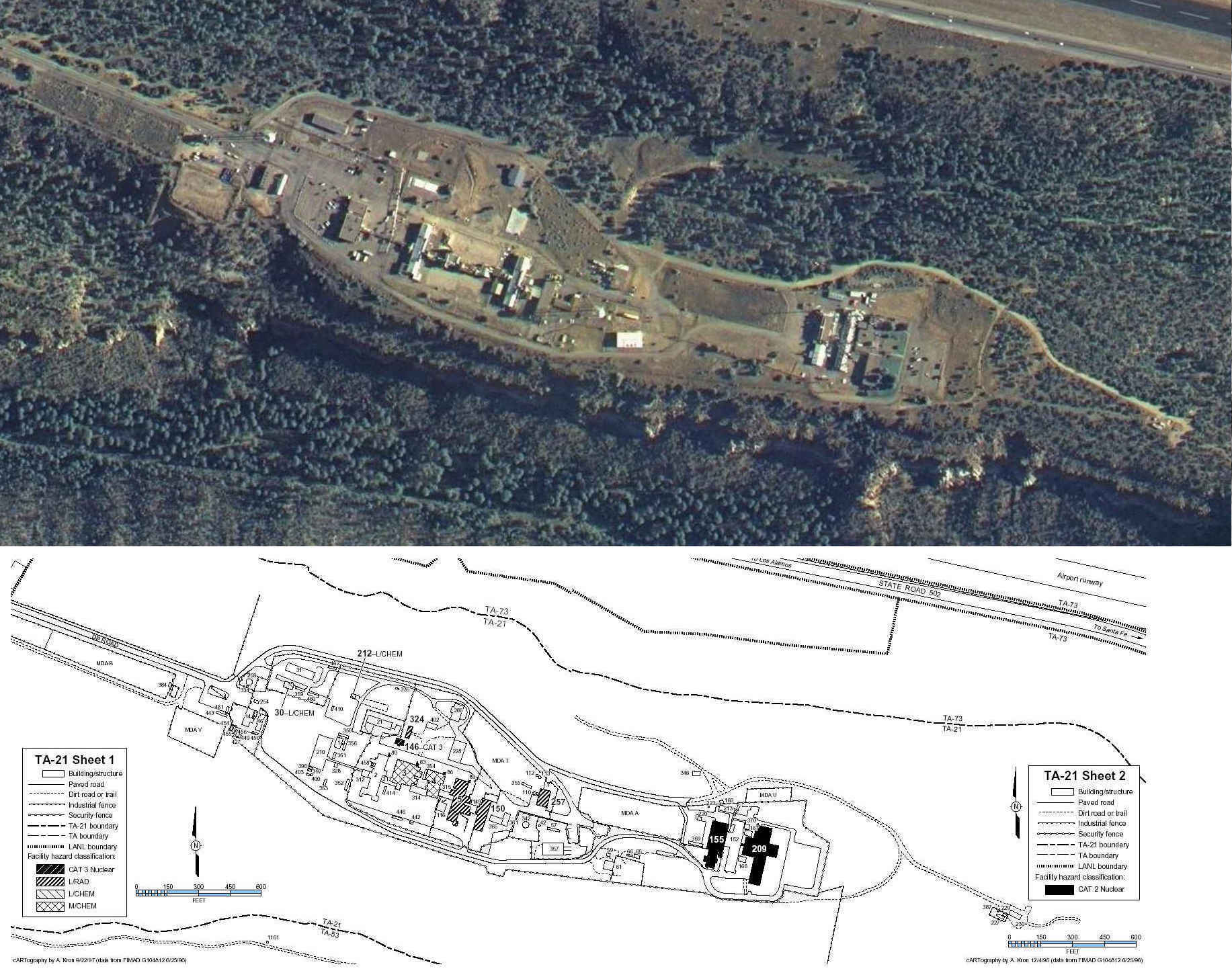
TA-21, called DP Site [Table 4-11 and Figure 4-13 (index map of TA-21)], has two primary research areas: DP West and DP East. DP West is the site of the former radioactive-materials-processing facility and is gradually being decontaminated and decommissioned. DP East consists of two tritium facilities that provide space for energy, environmental, and weapons defense research.
TA-21 is on DOE-controlled land approximately 0.6 mi (1 km) from the nearest residential area. A limited-access airstrip (TA-73) is located across a canyon, 0.37 mi (0.6 km) to the north, on a parallel mesa. The main public highway to the townsite runs along the north boundary of TA-21 parallel to the airstrip. TA-21 is isolated from other Laboratory facilities, and its only access route is through the Los Alamos townsite. Access to the fenced site is uncontrolled; building access is controlled by badge readers.
The Laboratory’s long-range plan is to close TA-21. Plans are currently under way to obtain funding and support to consolidate TA-21 tritium operations and activities at WETF. This consolidation project will result in an upgrading of tritium facility safety features, more cost-effective tritium operations, and improved efficiencies in tritium operations and programs. The project is envisioned as a consolidation that will result in new building construction, equipment changes, improved safety designs and capabilities, and some reconfiguration of tritium operations currently conducted at TA-21. Although processes and operations may be changed to incorporate new technology, the primary focus is on relocating existing TA-21 tritium process equipment and operations. This move will result in an increased tritium inventory at WETF (Section 4.11.2.1.1.1.1) and a reduced tritium inventory at the TA-21 Tritium Systems Test Assembly (TSTA) Facility and Tritium Science and Fabrication Facility (TSFF). Following relocation, the remaining facilities at TA-21 would become candidates for D&D, which would result in a short-duration increase in radioactive waste volumes for the affected facilities. The consolidation project could begin as early as 2000 and be completed by 2006. These planned actions would reduce the overall impact of tritium operations on the environment and the public.
4.13.2 Facilities Description
4.13.2.1 Facility Hazard Categories
Table 4-11 identifies the facilities at TA-21 that fall into a facility hazard category because of the type of operations performed in the facility.
![[Image]](lanl-ta-21-t411.jpg)
4.13.2.1.1 Nuclear Facility Hazard Categories
4.13.2.1.1.1 Hazard Category 2 Nuclear Facilities
Two Hazard Category 2 nuclear facilities are located at TA-21: the TSTA (Building 155) and the TSFF (Building 209, Figure 4-13, Sheet 2).
4.13.2.1.1.1.1 Tritium Systems Test Assembly
Planning for TSTA began in 1977 after LANL was chosen to develop, demonstrate, and integrate technologies related to the deuterium-tritium fuel cycle for large-scale fusion reactor systems. Construction was completed, and pretritium testing was initiated in 1982. The first tests with tritium in the system were conducted in 1984.
TSTA consists of a large gas loop that simulates the proposed fuel cycle for a fusion facility. The loop does not include any specific fuel injection system but is sufficiently versatile to allow systems to be added as the gas-handling system design requirements for fusion reactors are better defined. The gas loop is designed to handle up to ~360 moles/day of deuterium-tritium. This flow provides experience with operating a cycle on a scale that is near the full-scale cycles currently being addressed for the International Thermonuclear Experimental Reactor System. To accomplish this scale, TSTA requires an onsite tritium inventory of 180–200 g of tritium.
The main experimental tritium area (Room 5501) has a total of 1,129 ft2 (344 m2) of floor area. Two small laboratories used for nonloop experiments are connected to the ventilation system for Room 5501, which also services the main experimental tritium area. In the same building, but in the area surrounding the main experimental area, are an additional 1,828 ft2 (557 m2) of floor area, which is used for the control room, support center, office area, equipment rooms, an uninterrupted power supply, and a diesel generator. Another part of the building, used for offices and shops, contains 1,165 ft2 (355 m2).
In addition to the main building, 459 ft2 (140 m2) of storage space is available in a metal warehouse (Building 213) located directly north of the main experimental area. The east end of this building has been sectioned off and is used as a storage area for tritium-contaminated equipment. A portable building (Building 369) located on the west side of the main laboratory provides an additional 230 ft2 (70 m2) of office space. The outside dimensions of the part of the building that houses the main experimental area are 77 ft (23.5 m) by 36 ft (11 m). The walls are constructed of 7.9-in. (20-cm) concrete masonry block.
Concrete masonry units are reinforced with No. 4 deformed reinforcing bars, placed vertically at 32 in. (81 cm) on center, and truss-type reinforcing placed horizontally at alternate courses. The floors are 3.9-in.- (10-cm-) thick concrete on grade. The roof is 3.2-in. (8-cm) Tectum Tile T-300 and Tectum Plank P-300 over structural steel members. The main experimental area is 95 ft (29 m) long by 39.4 ft (12 m) wide and has a steel platform (mezzanine) 9.8 ft (3 m) above the floor that provides a total of 656 ft2 (200 m2) of floor space. Below the eastern portion of the mezzanine is a 4.9-ft- (1.5-m-) deep pit lined with concrete, whose width is 14.4 ft (4.4 m) and whose length is all but 5.9 ft (1.8 m) of the length of the mezzanine. The minimum height of the main floor of the test cell to the ceiling is 26 ft (8 m) at the sides of the room, and the height increases to 28 ft (8.5 m) at the center of the room. When required, an additional 4.9 (1.5 m) of ceiling height can be provided by the pit. An additional service pit 3.9 ft (1.2 m) in diameter by 20 ft (6.1 m) deep provides space for lowering the distillation column vacuum jacket of the isotope separations system. The ceiling height of the rooms surrounding the test cell is 13 ft (4 m).
Environmental and safety systems at the TSTA ensure personnel safety and minimal tritium release. The TSTA Project has been instrumental in developing and integrating these systems following a philosophy of redundant containment, detection, and recovery. The environmental and safety systems used at TSTA provide secondary containment for processing equipment, glovebox and gaseous effluent detritiation, room air detritiation, tritium monitoring, portable ventilation ducting, supplied-breathing-air system, and solid and liquid waste minimization and disposal. All significant quantities of tritium are triply contained; the building acts as the third and final barrier. The triple containment makes the probability of accidental releases into the environment extremely low. One stack, located in the northwest corner of Building 155, services the TSTA tritium-handling areas.
4.13.2.1.1.1.2 Tritium Science and Fabrication Facility
The Tritium Science and Fabrication Facility (TSFF) (Building 209) is a tritium research and development facility. The building is located east of the TSTA at the DP East research area. Built in 1964 as a chemistry process building, it was modified in 1974 to accommodate tritium salt synthesis and to provide physical preparation of the underground nuclear testing program. The salt synthesis work was discontinued in 1993 in response to the cessation of nuclear testing, and the facility’s name was changed from the Tritium Salt Facility to the TSFF.
The current mission of the TSFF is to support DOE and LANL by providing experimental services such as neutron tube target loading, mass spectrometry, getter research, metal melt/tritium recovery, inertial confinement fusion target studies, calorimetry, salt line D&D, generic experiments on effluent treatment systems, and tritium storage. In the late 1990s, the neutron-tube-target-loading function will be relocated in part of WETF. To accomplish these program missions and operational capabilities, the TSFF requires an inventory of 366 g of tritium, primarily in gaseous form. Additional tritium inventory (mainly tritium gas and tritium adsorbed on solid metal storage beds) is maintained in the storage area at the TSFF. This tritium inventory is maintained in storage/shipping containers awaiting processing and/or transport to other locations.
The TSFF is a 3,000-ft2 (300-m2) block-walled portion of Building 209, which is a one-story building with a basement. TSFF is located at the north end of the building and is divided into several laboratory rooms. The floor consists of 6-in.- (15.2-cm-) thick, reinforced-concrete slab supported by reinforced-concrete beams, columns, and basement walls that extend to tuff below. The TSFF is located approximately 150 ft (46 m) east of the TSTA. The two facilities are connected by a spinal corridor, which also connects with adjacent office and nontritium laboratory areas.
Tritium experiments at the TSFF are performed in gloveboxes or in fume hoods, depending on the amount of tritium being handled and process needs. The TSFF is serviced by an exhaust ventilation system that discharges to a 75-ft- (22.9-m-) high exhaust air stack. This stack, as well as the general room air, is continuously monitored for tritium content. The glovebox atmospheres are also monitored for tritium, and the exhaust streams are processed by an effluent treatment system.
4.13.2.1.1.2 Hazard Category 3 Nuclear Facility
Building 146 (Figure 4-13, Sheet 1) is categorized as a Hazard Category 3 nuclear facility. This building is an old exhaust filter building that has been decontaminated and is awaiting DOE approval of its reclassification from a nuclear facility to a nonhazardous facility.
4.13.2.1.2 Non-Nuclear Facility Hazard Categories
4.13.2.1.2.1 Buildings Categorized M/CHEM
Two buildings at TA-21 are categorized as M/CHEM (Figure 4-13, Sheet 1). Buildings 3 and 4 were laboratory buildings that housed the Enriched-Uranium-Processing Facility. Operations at this facility ceased in July 1984, and the buildings were maintained under shutdown surveillance until decommissioning began. Decommissioning began in 1994 with Buildings 3 and 4 South. All contaminated and uncontaminated equipment—hoods, gloveboxes, tanks, and piping—was removed, and the buildings’ walls and ceilings were cleaned. The buildings were then razed, and the utility tunnels under the buildings, exhaust ventilation ductwork, and stacks were removed.
Decommissioning was completed in 1995. Decommissioning at TA-21 West is continuing as funding is available. It is expected that remediation work will continue on Buildings 3 and 4 North.
4.13.2.1.2.2 Buildings Categorized Low Hazard
Six buildings (Figure 4-13, Sheet 1) at DP West have been categorized as low hazard (L/RAD and L/CHEM) and are gradually being decommissioned. They include laboratory buildings (Buildings 5 and 150), which contain radiation and chemical hazards; the paint shop (Building 30), which contains chlorine gas (chemical) hazards; a filter building (Building 324), which contains residual radio-nuclides; the Calcium Building (Building 212), which contains chemical contaminants; and the waste disposal plant (Building 257).
4.13.2.2 Nonhazardous Facilities
Seventy-four administrative, technical, physical support, and other buildings and structures categorized as nonhazardous are located at TA-21.
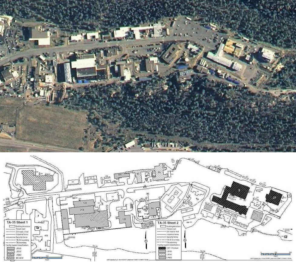
4.17.1 Site Description
TA-35 [Table 4-15 and Figure 4-17 (index map of TA-35)] is used for nuclear safeguards research and development, primarily in the areas of lasers, physics, fusion, materials development, and chemistry research and development. Additional activities include research in reactor safety, optical science, and pulsed-power systems. Metallurgy, ceramic technology, and chemical plating also occur at this site.
4.17.2 Facilities Description
4.17.2.1 Facility Hazard Categories
Table 4-15 identifies the facilities at TA-35 that fall into a facility hazard category because of the type of operations performed in the facility.

TA-35 is the location of the proposed Atlas Facility, which will use portions of existing Buildings 124, 125, 126, 294, and 301. These facilities currently support the National High-Magnetic-Field Laboratory (NHMFL) and other research activities. Atlas operations will require the following major special facilities equipment elements: 1,430-MW generator (existing at TA-35); 80-MW alternating-current to direct-current converter; 50-MJ inductive energy transfer system; 36-MJ capacitor bank; target chamber; and various types of control, diagnostic, and data acquisition equipment.
All special facilities equipment and supporting facilities/infrastructure currently meet or will be designed to meet the requirements for a low-hazard facility. Additional information on Atlas can be found in DOE’s Final Programmatic Environmental Impact Statement for Stockpile Stewardship and Management (DOE 1996).
For the purpose of this document, Buildings 125, 125, 126, 294, and 301 are treated as pulsedpower facilities and are discussed together in the following sections.
4.17.2.1.1 Nuclear Facility Hazard Categories
TA-35 contains two facilities (Buildings 2 and 27) currently categorized as Hazard Category 3 nuclear facilities. The major purpose of both buildings is to support nonproliferation and international security research. Other R&D includes various studies of radiation effects on materials, which are conducted under fusion and ceramic science and technology programs. These buildings are used primarily for R&D, engineering, technology transfer, and training for nondestructive assay related to nuclear safeguards and hazardous materials.
4.17.2.1.1.1 Hazard Category 3 Nuclear Facilities
4.17.2.1.1.1.1 Nuclear Safeguards Research Building
The Nuclear Safeguards Research Building (Building 2, Figure 4-17, Sheet 2) contains approximately 82,000 ft2 (24,994 m2) of floor space and is primarily constructed of reinforced concrete and concrete block. The roof is constructed of stressed-concrete T-beams with a built-up roofing system.
The building contains three wings; Wings A and C have basements. Wing A, which contains a high bay with massive reinforced-concrete walls at the east end, is used for the Isotopic Fuels Impact Test Facility, also known as the 7-in. launcher. The 7-in. launcher is used to impact 238Pu heat sources, fuel materials, structural materials, and subassemblies of isotope generators to determine their responses to impacts and the effects on different target materials. Most of the office spaces for Building 2 are located in Wing B. Wing C and the remaining portion of Wing A house two major R&D programs: radiation effects in ceramics and fusion materials. An SNM vault is also provided.
4.17.2.1.1.1.2 Nuclear Safeguards Research Building
Building 27 (Figure 4-17, Sheet 2), which contains approximately 45,000 ft2 (13,716 m2) of floor space, is a three-story sheet metal, steel, and concrete block building. Levels 2 and 3 are underground. The roof is supported by steel beams. Some portions of the roof system are composed of sheet metal and others of built-up roofing. The underground areas are enclosed by massive reinforced-concrete walls.
The primary activities in Building 27 are nuclear safeguards research, development, and training, which address new ways of conducting nondestructive analysis (NDA) tests on samples of many different sizes and shapes to determine their uranium and plutonium content. This R&D is supported by electronics development, mechanical design and fabrication, and administrative activities.
The main SNM vault is located in the third floor of the building, and an alternate vault is located on the first floor.
All radioactive sources and SNM are encapsulated to prevent any contamination of workers or the facility. The uranium in this facility is singly contained, and plutonium is doubly contained. No nuclear material is processed, and samples remain sealed at all times, including when they are used in instruments. SNM is used as a radiation source for calibrating and testing the performance of prototype and finished instruments, as well as for the Nuclear Safeguards Technology Training Program.
4.17.2.1.2 Non-Nuclear Facility Hazard Categories
4.17.2.1.2.1 Building Categorized M/CHEM
The Target Fabrication Facility (TFF) (Building 213, Figure 4-17, Sheet 1) is located in TA-35, about 1.25 mi (2 km) southeast of the central technical area (TA-3) off Pajarito Road on Pecos Road. It is immediately to the east of TA-55 and directly north of TA-50. TFF is a restricted area surrounded by a security fence with controlled access. At one time, the facility contained tritium. The last of the tritium was removed in 1993.
The two-story structure is approximately 61,000 ft2 (18,593 m2) with approximately 48,000 ft2 (14,630 m2) of laboratory area and 13,000 ft2 (3,962 m2) of office area. In general, the structure is reinforced concrete with isolated concrete floor slabs for vibration-sensitive equipment. The HVAC system maintains a negative pressure in the laboratories, venting both room air and hood exhaust to the atmosphere through filtered and monitored exhaust stacks. Sanitary waste is piped to the sanitary waste disposal plant near TA-46. Radioactive liquid waste and liquid chemical wastes are shipped to TA-50.
The TFF laboratories and shops are specialized to provide precision machining, polymer science, physical vapor deposition, chemical vapor deposition, and target assembly, which are supported by industrial collaborations and energy, environment, nuclear weapons, and conventional defense programs.
Potential hazards related to operations performed at TFF include handling toxic chemical vapors and liquids associated with electroplating and other coating and fabricating processes. The potential for explosions caused by releases of hydrogen or other explosive chemicals exists at this facility.
4.17.2.1.2.2 Building Categorized L/ENV
Building 85 (Figure 4-17, Sheet 1) was originally designed to produce high-energy, high-frequency laser radiation. Several names have been associated with the building (the Mercury Laser Laboratory, the Advanced Laser Laboratory, and the Chemical Laser Laboratory). The building is modified periodically to meet new laser research criteria.
4.17.2.1.2.3 Building Categorized L/RAD
The Air Filter Building (Building 7, Figure 4-17, Sheet 2) is an old filter building that was part of the physical support facilities at TA-35. The ductwork still contains plutonium contamination.
4.17.2.1.2.4 Buildings Categorized L/ENS
4.17.2.1.2.4.1 Pegasus II Facility
The Pegasus II Facility (also called the Laboratory and Office Building) (Building 86, Figure 4-17, Sheet 2), a pulsed power facility, features a capacitor bank consisting of 8 Marx modules that store up to 4.3 MJ of electrical energy. The facility houses experiments in hydrodynamics and radiation transport.
4.17.2.1.2.4.2 Pulsed-Power Facilities
Buildings 124 and 125 (Figure 4-17, Sheet 1) were constructed in 1980 to house the Antares Project, a laser-fusion project. Buildings 294 and 301 were constructed in 1990 as part of a more recent project that uses a 1,430-MVA generator. Currently, these facilities are used to support the NHMFL’s Pulsed-Field Facility.
The Pulsed-Field Facility is one of three components of the NHMFL; the other two are at Florida State University at Tallahassee (continuous fields, magnetic resonance, and general headquarters) and the University of Florida at Gainesville (ultralow temperatures at high magnetic fields). The National Science Foundation and the DOE are the primary sponsors of NHMFL.
The Pulsed-Field Facility is a general-user facility, open on a proposal review basis to all researchers who wish to perform experiments in high magnetic fields. The great majority of experiments are directed at studying the materials and physics of condensed matter. In condensed matter and materials research, pulsed fields are useful primarily for reaching higher fields than it is possible to reach with steady-state magnets, which are limited to 2 Tesla for permanent magnets, 20 Tesla for superconducting magnets, 33 Tesla for water-cooled resistive magnets, and 45 Tesla for hybrid magnets (a combination of the superconducting and resistive magnets). [One Tesla is equal to 10,000 oersteds or, in vacuum, 10,000 G. The earth’s magnetic field is about 1/4 to 1/2 G.]
This set of facilities is the location of the proposed Atlas Project (Section 4.17.2.1). The NHMFL will continue to use the generator when it is not serving the Atlas Project. A firing site (PT-6) at TA-39 also supports the NHMFL (Section 4.20.2.1.2.2.1).
4.17.2.1.2.4.3 Buildings 124 and 125
Buildings 124 and 125 (Figure 4-17, Sheet 1) have the following special features: Both buildings were designed for large-scale experimental work and both feature high ceilings with heavy-duty gantry cranes that can access the entire interior space. Both buildings were designed to house the power amplifiers and target chamber of a laser fusion facility. To protect the public from the potential hazards of this work, the buildings were constructed with concrete walls and roofs. This type of construction is ideal for a high-energy capacitor bank because shrapnel caused by possible defects will be contained within the building. The walls and ceiling will also contain any diagnostic x-rays produced. Building 124 has an electrically shielded data acquisition room that is protected by a concrete wall. This room satisfies the requirement for a secure site for classified data. Building 125 has a 282-ft2 (86-m2) electrically shielded control and data acquisition room. This room satisfies the requirements for machine control and unclassified data acquisition
4.17.2.1.2.4.4 Building 294
Building 294 (Figure 4-17, Sheet 1) is constructed of steel framing with synthetic stucco panels at the east and west ends. The building fills the space between Building 124 to the north and Building 125 to the south and shares the exterior north and south walls of these buildings. The building currently houses the power supply for the Pulsed-Field Facility.
4.17.2.1.2.4.5 Building 301
Building 301 (Figure 4-17, Sheet 1) is a 3,566-ft2 (1,087-m2), preengineered steel building set on a concrete pad. The building, which houses a 1,430-MVA generator, has several significant features to isolate generator vibrations from surrounding buildings. The generator and associated controls and alarms currently support the Pulsed-Field Facility.
4.17.2.1.2.4.6 Physics/Laser Building
The Physics/Laser Building (Building 128, Figure 4-17, Sheet 1) is an experimental science laboratory.
4.17.2.1.2.4.7 Trident Laboratory
Trident (Building 189, Figure 4-17, Sheet 1) is a multipurpose laboratory for developing instrumentation and conducting experiments requiring high-energy-laser light pulses. It is operated primarily for inertial confinement fusion research, weapons physics, and basic research and features flexible-driver characteristics and illumination geometries, broad resident diagnostic capability, and flexible scheduling. The facility includes a frequency-doubled, neodymium-glass laser driver; a high-vacuum target chamber; a basic optical and x-ray diagnostic suite; and ancillary equipment and facilities.
4.17.2.1.2.4.8 Experimental Support Building
The Experimental Support Building (Building 207, Figure 4-17, Sheet 1) is an experimental science laboratory.
4.17.2.2 Nonhazardous Facilities
Approximately 123 other facilities at TA-35 are categorized as nonhazardous.
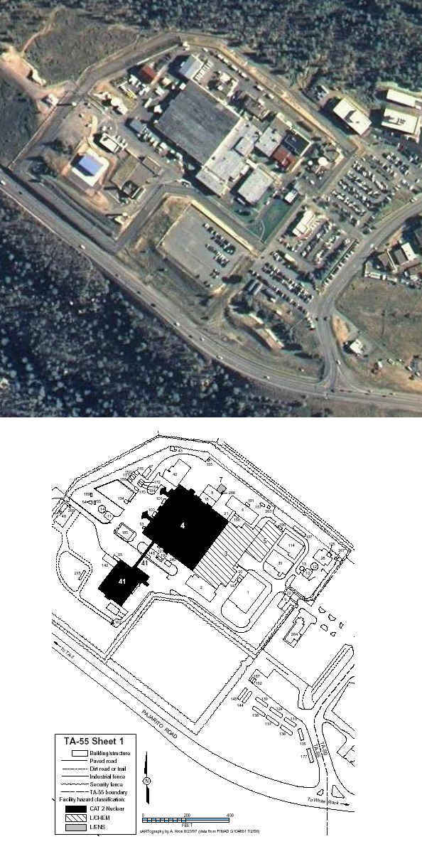
4.32.1 Site Description
The Plutonium Facility Site at TA-55 [Table 4-28, Figure 4-32 (index map of TA-55)] is located on 40 acres (16.18 ha) about 1 mi (1.6 km) southeast of the central technical area (TA-3). Most of TA-55 is situated inside a restricted area surrounded by a double security fence. The main complex has five connected buildings: the Administration Building (Building 1), the Support Office Building (Building 2), the Support Building (Building 3), the Plutonium Facility (Building 4), and the Warehouse (Building 5). The Nuclear Materials Storage Facility (Building 41) is separate from the main complex but shares an underground transfer tunnel with Building 4. Various support, storage, security, and training structures are located throughout the main complex.
4.32.2 Facilities Description
To meet the varied needs of research and development and plutonium-processing programs at the Laboratory, TA-55 provides chemical and metallurgical processes for recovering, purifying, and converting plutonium and other actinides into many compounds and forms. Additional capabilities include the means to safely and securely ship, receive, handle, and store nuclear materials, as well as manage the wastes and residues produced by TA-55 operations. A core capability is basic and applied research in plutonium and actinide chemistry.
Core competencies are maintained in the Plutonium Facility for each type of plutonium-processing activity. Extensive plutonium recovery processes are maintained, as well as the ability to convert the recovered material to plutonium metal. A separate portion of the facility is dedicated to fabricating ceramic-based reactor fuels and to processing 238Pu used to produce radioisotope heat sources. In addition, analytical capabilities, materials control and accountability techniques, and a substantial R&D base are available to support these core capabilities.
A sophisticated nuclear materials measurement and accountability system is used at TA-55. The system includes nuclear materials accounting, nuclear materials management and modeling, a measurement support operation, operation of a nondestructive assay laboratory, nuclear materials packaging and transfer, and nuclear materials storage. All nuclear materials that are in process or are stored onsite are monitored to ensure that material balances are properly maintained and inventoried on a real-time basis. The nuclear-materials-packaging and transfer operation receives nuclear material into the facility and transfers shipments out of the facility. The nuclear materials storage operation provides a safe storage location for the actinide materials at the Plutonium Facility.
The Plutonium Facility has extensive capabilities for treating, packaging, storing, and transporting the radioactive waste produced by TA-55 operations. Liquid wastes are converted to solids or are piped to the RLWTF at TA-50. Some solid TRU wastes are immobilized in cement in 55-gal. (208-L) drums. Other TRU waste is consolidated in 15-gal. (57-L) or 30-gal. (114-L) drums or is packaged in waste boxes. Low-level wastes are also packaged at this facility. Solid wastes of all types are stored at TA-55 until they are shipped to Laboratory waste storage or disposal locations, primarily at TA-54.
4.32.2.1 Facility Hazard Categories
Table 4-28 identifies the facilities at TA-55 that fall into a facility hazard category because of the type of operations performed in the facility.
![[Image]](lanl-ta-55-t428.jpg)
4.32.2.1.1 Nuclear Facility Hazard Categories
The Plutonium Building (Building 4) is categorized as a Hazard Category 2 nuclear facility. Although not currently operational, the Nuclear Materials Storage Facility will also be a Hazard Category 2 nuclear facility and is shown as such on the accompanying maps.
4.32.2.1.1.1 Plutonium Building
Plutonium processing is performed in the Plutonium Building (Building 4, Figure 4-32, Sheet 1), which is a two-story laboratory of approximately 151,000 ft2 (46,025 m2). The exterior walls and roof are of reinforced concrete. A concrete fire wall divides the building into two halves, each of which contains its own ventilation systems and electrical substations. One half of the process floor is divided by a central corridor into Areas 100 and 200. This half contains the plutonium research and development laboratories, the 238Pu operations, and the personnel decontamination area. The other half is divided into Areas 300 and 400 by another corridor. This half houses plutonium recovery, metal preparation and fabrication, and nondestructive analysis laboratories.
Each of the processing areas is further divided into a number of rooms that contain the gloveboxes for plutonium work. The ventilation systems that service the gloveboxes and all other utilities are located in the basement of the facility. The basement also houses critical support equipment, including all other ventilation equipment, the packing/unpacking room, waste-handling areas, the isopress laboratory, and the plutonium storage vault.
Three levels of containment are provided for plutonium processing. The primary confinement system includes gloveboxes, hoods, vessels, tanks, piping, and the glovebox ventilation exhaust system. The secondary confinement system includes the walls, floors, ceiling, and doors of the laboratories containing the gloveboxes, as well as the laboratory recirculation and bleed-off exhaust system. The exterior walls, floor, roof, and doors of the structure, along with the basement exhaust system, provide the tertiary confinement system.
The ventilation system in the facility has four zones, all of which are maintained at a lower pressure than that of the outside air. Air enters the two halves of the facility through an intake stack that has four ducts. Two ducts supply air to each half of the building. The ventilation system is designed so that each zone operates as a separate building with its own filtered exhaust stack. Exhaust from each confinement area is sent through at least two stages of HEPA filtration to prevent radioactive particles from being discharged to the environment.
The conveyor system in the facility transports contaminated material and equipment to almost any point on the first floor. Elevated stainless steel tunnels equipped with a trolley hoist system connect the gloveboxes. The vertical portions of the tunnels connect the overhead system to the gloveboxes at drop boxes located on the first floor. These drop boxes are the transfer points in which items are hoisted up to the trolley in the overhead tunnel system for eventual offsite waste disposal.
The criticality detection system monitors operations on the main processing floor of the Plutonium Facility and in the basement vault to detect gamma energy released from fission of SNM. The system is designed to detect conditions that could lead to a criticality accident in this facility and to sound an audible alarm. The alarm initiates immediate evacuation to minimize personnel exposure. This system consists of 20 Geiger-Mueller detector heads and associated circuitry located throughout the first-floor process areas and basement vault.
A continuous air-monitoring system is used to sample and analyze air from multiple points throughout the laboratory areas, basement, ductwork, and exhaust stacks. A continuous stream of sample air is drawn to a solid-state alpha detector, whose data are used for man/machine interface (lights, meter, squealer) and for monitoring by the operations center.
Other supporting systems include fire detection and suppression systems, a chilled-water system, an instrument air system, electrical power, water distribution systems, and a vacuum system. Voice communication is provided by a paging system and a telephone system. The emergency system provides paging throughout the TA-55 area and sounds the criticality and fire alarms.
4.32.2.1.1.2 Nuclear Materials Storage Facility
The Nuclear Materials Storage Facility (Building 41, Figure 4-32, Sheet 1) will eventually contain a significant amount of stored nuclear material. This facility is primarily intended for intermediate and long-term storage of SNM. Although completed in 1987, the Nuclear Materials Storage Facility has never operated because of design and construction deficiencies. A major renovation project is being planned to correct those deficiencies so that the facility can operate. The renovation project is expected to be completed by 2001.
4.32.2.1.2 Non-Nuclear Facility Hazard Categories
Two facilities, Buildings 3 and 5, are categorized L/CHEM, and one facility, Building 7, is L/ENS. Building 3 (the Support Building) contains some laboratories that use chemicals. Building 5 (the Warehouse) is used to store chemicals. Building 7 (the Calcium Building) is used to store calcium (Figure 4-32, Sheet 1).
4.32.2.2 Nonhazardous Facilities
Approximately 55 other facilities exist at TA-55, all of which have been categorized nonhazardous. These buildings are administrative, technical, and general storage buildings; passageways; and pump stations.